Potentiometer
Historical document, translated for reference. It reflects medical knowledge of the 1920s–30s and is not medical advice.
Summary
A device for measuring electrical potentials or electromotive forces (EMF) using the Poggendorf-Dubois Reymon compensation method. Used in physico-chemical and biological-medical applications, particularly for measuring ion concentrations like pH.
Encyclopedia article (1928–1936)
POTENTIOMETER, an apparatus used for measuring electrical potentials, i.e., electromotive forces (EMF). For this purpose, voltmeters are usually used. But in certain cases, for example when measuring the EMF of concentration elements, it is necessary to avoid the expenditure of electrical energy during measurement, since this would affect the magnitude of the measured EMF in cases of small current strengths. In these cases, POTENTIOMETER
«08
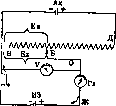
voltmeters are not suitable, and the measurement must be performed using the Poggendorf-Dubois Reymon compensation method, which forms the basis of the operation of the P. The current under investigation is sent through circuit IEBV (Fig. 1), and into this circuit is included some instrument registering the presence or absence of current (zero instrument). The potential difference between points B and V represents the desired EMF-Ex; this EMF, of course, does not change, no matter where the movable contact B is located. Opposite to the accumulator, current is sent through circuit AkDBV, which is known to be stronger, and its potential drop occurs along the resistance DV. By moving the movable contact B, we change that part of the EMF of this circuit which passes along the common to both circuits section of the path BV. Thus, it turns out that between points B and V there are, as it were, 2 potential differences: one constant Ex, coming from the first circuit, the second - let us call it Ea, coming from the second circuit and changing depending on the position of point B. If Ex>Ea, then the current in the first circuit will go in the usual direction of the arrows (if we indicate the flow of electrons); if Ex<Ea, then the current in the first circuit will go in reverse, since the negative current from the accumulator will flow in the direction of ApVIEZB, and the element IE will represent an electrolyzable system. If Ex=Ea,
Figure 1. Potentiometer device with voltmeter: Ak-accumulator; IE-investigated element; Gl-galvanometer; V-voltmeter.
then there will be no current in the first circuit - the zero instrument will show no current between points B and Z. Now, in order to find Ex, it is necessary to measure the equal to it Ea; this is done differently in various models of potentiometers. As already mentioned, P. is often used for measuring the EMF of concentration elements, and the ultimate goal is not the measurement of the electromotive force of such a system itself, but the determination of the concentration of ions in it, for example the concentration of H-ions (pH), and therefore potentiometers specially designed for this purpose are often called ionometers. It is clear that electromotive forces can be measured by the Poggendorf compensation method without any P., but by using assembled setups with a rheochord or resistance stores (according to Michaelis) with a capillary electrometer or galvanometer as zero instruments, with switches and many openly laid wires. Fundamentally, P. represents such setups, with the difference that in them all parts are firmly, compactly and most conveniently for rapid measurement once and for all connected and enclosed in a box. When removing the cover of this box, only a few handles and contacts and sometimes the measuring instruments enclosed here become visible on a board of insulating material. Thus, all the critical parts of the compensation setup are protected from dust and moisture, and the entire setup becomes portable. In the market there is a whole range of models of P., designed for various purposes: physico-chemical, biological-medical (measurement of pH), technical (determination of concentration of all sorts of ions and various electrometric titrations), etc. They differ from each other in accuracy of determination, method of reading, method of checking, resistance used, zero instruments, arrangement scheme, etc. The most common and original are the following models. 1. Perhaps the simplest apparatus is one in which the EMF (Ea) is directly measured in the compensation position with the help of a sensitive voltmeter (Fig. 1).--2. One can proceed somewhat differently, namely for the compensation position measure the current strength I in the second circuit with the help of a sensitive ammeter in amperes and the resistance R of section DV in ohms (Fig. 2). The product of these two quantities will give the desired EMF: IR=Ex. The two described methods of setup without a normal element are used in American P. However, they cannot be considered especially accurate, first because it often happens that the magnetic system of measuring instruments changes somewhat over time, and second because the scale of the instrument must be divided extremely finely in order to be able to calculate Ex with sufficient accuracy. They are used, especially the first setup, for electrical titrations.-3. There are models that are closest to ordinary electrometric compensation setups.
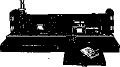
,-----=^£±-------wywv B AWWWWWWVVWVW BKWWWWWWWWWWVWl Б* -Г1-И9+X_ т+нэ J-Lj Lrt д Figure 2. -o Гл Figure 3. K* 9 °3 Figure 2. Potentiometer device with ammeter: Ak-accumulator; IE-investigated element; Gl-galvanometer; DV-resistance; A-ammeter. Figure 3. Potentiometer device with rheochord, additional resistance and normal element: Ak-accumulator; IE-investigated element; NE-normal element; Gl-zero instrument; DV-rheochord 1 018.7 mm; DS-additional resistance. In them, resistance wire with divisions-rheochord-1018.7 mm long is used as resistance, in addition, additional resistance is included in the second circuit, and in the first, instead of the investigated element, a normal element can be included (Fig. 3). Sending current from the normal element (voltage 1018.7 mV) through the path IEZDV in the first circuit, the compensation position is achieved with the help of the additional resistance DS. Now each millimeter of the rheochord corresponds to a potential drop in the second circuit of 1 mV. Turning off the normal element, current from the investigated element is sent through the path IEZKBV in the first circuit and a new compensation position is found by moving the slider B. The desired EMF-Ex, expressed in millivolts, is equal to the number of mm of the rheochord on the section BV. Thus, the EMF can be easily read with an accuracy of 1/3 mV. Among individual models, one can mention: electroionometer of Luers (H. Luers) of the Lautenschleger firm (F. & M. Lautenschlager), which in essence is an electrometric setup assembled on one board (Fig. 4), more suitable for technical purposes the potentiometer of Emslander (EmsUnder) №9 «14» of the Kohler firm (F. Kohler); microionometer of Lautenschleger, an instrument in which the resistance wire of 1018.7 ohms is wound in the form of a spiral (there is no classic slider), and the capillary electrometer can be replaced by a galvanometer,- which results in a very portable apparatus (Fig. 5).
Figure 4. Electroionometer of Luers.
Figure 5. Microionometer of Lautenschleger.
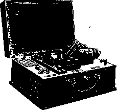
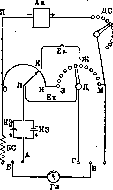
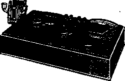
The 4th group includes models in which instead of rheochords there are rheostats with rotating handles (curb rheostat). Usually in them there is placed 1 rheostat of 1 000 or 1 100 ohms (Fig. 6, M3) with 10 divisions of 100 ohms each and a resistance spiral of 100 ohms (IO); thus in the first circuit any resistance from 0 to 1100 or even 1 200 ohms can be included. These P. are supplied with additional resistance DS, galvanometers as zero instruments and normal elements. The method of working with them is analogous to the one just described for group 3. Only in this case, when compensating the normal element in the first circuit, a resistance of 1018.7 ohms must be included, then 1 ohm of resistance corresponds to 1 mV. The desired EMF Ex, expressed in millivolts, is equal to the number of ohms of resistance in the section connected to the galvanometer, on the section ZK. One can mention the following models: P., manufactured by the Main Chamber of Weights and Measures in Leningrad; potentiometer of Mislowitzer (Mislowitzer), manufactured by the Leitz firm (Fig. 6 and 7) with a special galvanometer for it, which by including in front of it a large ballast resistance of 100 000 ohms, located in the potentiometer box (Fig. 6. BS), is transformed from a zero instrument into a voltmeter, and then can serve instead of a normal element for quick checking of the EMF passing through the entire resistance (1 100 mV):; -
Figure 6. Device of the Mislowitzer potentiometer: Ak-accumulator; IE-investigated element; NE-normal element; Gl-galvanometer; M3-rheostat with divisions of 100 ohms; IO-resistance wire; DS-additional resistance; BS-ballast resistance-
Figure 7. Potentiometer of Mislowitzer.
is found in many scientific-medical laboratories. Potentiometer of Truna and
Figure 8. Potentiometer of Truna and Tødta.
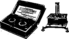
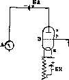
The Theda (Thrun, Todt) model by Leitz. In this model, both the galvanometer and the normal element are built into one case with the P. itself (fig. 8). The P. of the American firm Leeds and Northrup in Philadelphia, distinguished by the accuracy of EMF reading (up to 0.01 mV). Suitable for physicochemical research. -5. Finally, mention should be made of another recent construction of the ionometer - the Stato-Ionometer by Wulf - by the firm Lautenschläger, which is based on a vacuum tube voltmeter. The potential to be measured is connected to the grid and to the negative end of the filament of the electron tube (fig. 9). When the filament is heated, a current flows from k to A, supplied by battery BA; the strength of this current can be measured by an ammeter A; it turns out to depend on the voltage on the grid. Thus, the EMF of the element under investigation can be determined from the strength of the anode current and read directly on a correspondingly graduated measuring instrument. It should be added that in this method, as little current is taken from the current source of interest as in the compensation method. This method allows for the direct registration of pH on a rotating drum (fig. 10). Such
pH curves are very convenient for electrometric titration. The accuracy of the latest construction of this instrument is not lower than that of other potentiometer models. Lit - Walter O., Methods for determining the concentration of hydrogen ions, L., 1932; Mislovitzer E., Determination of the concentration of hydrogen ions in liquids, L., 1932.
Figure 9. Circuit diagram of a vacuum tube potentiometer: E - electron tube; a - anode; k - filaments; r - grid; ИЭ - element under investigation; A - ammeter; БН - filament battery; BA - anode battery.
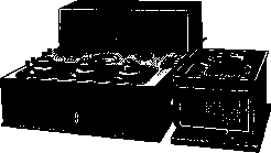
Figure 10. Wulf's statioionometer.
pH curves very convenient for electrometric titration. The accuracy of the latest construction of this instrument is not lower than that of other potentiometer models. Lit - Walter O., Methods for determining the concentration of hydrogen ions, L., 1932; Mislovitzer E., Determination of the concentration of hydrogen ions in liquids, L., 1932.
Related articles
Mentioned in
Cite this page
“Potentiometer.” Soviet Medical Encyclopedia. English translation of Bolshaya Meditsinskaya Entsiklopediya, 1st ed. (Moscow, 1928–1936), ed. N. A. Semashko. https://sovietmedicalencyclopedia.pages.dev/article/potentiometer/