Gas Masks
Historical document, translated for reference. It reflects medical knowledge of the 1920s–30s and is not medical advice.
Summary
Gas masks are devices designed to protect the respiratory organs from poisonous substances in the air. This article describes the historical development of gas masks from World War I through the 1930s, including both filtering and isolating types, with detailed information on their construction and effectiveness against various chemical agents.
Encyclopedia article (1928–1936)
Gas masks, devices serving to protect the respiratory organs from poisonous substances present in the air. The presence of a facial part (mask, helmet) in the gas mask simultaneously ensures protection for the eyes and face. Before the war of 1914-18, none of the warring states had any gas masks except for oxygen devices used in the mining industry. The use of combat poisonous substances (see) as a means of attack necessitated the development of corresponding measures for protection, both for individual soldiers (individual protection) and for entire groups of them (collective protection). Among these measures, gas masks occupy an exceptional position, being the primary means of chemical defense. By the method of protecting the respiratory pathways from the effects of poisonous substances (OV), gas masks are divided into two types: filtering gas masks and isolating gas masks (worn oxygen devices). In the former, purification of the air from poisonous impurities is achieved by filtering it through various media that absorb these impurities. In the latter, protection is achieved by complete isolation of the respiratory pathways from the surrounding atmosphere. Filtering gas masks, in turn, are divided into wet and dry gas masks. Wet filtering gas masks, which were the earliest means of protection, consisted of several layers of gauze soaked in one or another OV-neutralizing composition. The first samples of wet gas masks were bandages covering the nose and mouth. The impregnating composition contained substances that absorb chlorine, for example, sodium hyposulfite-30.0, soda-15.0, glycerin-10.0, water-45.0. The unreliability of the bandage's attachment to the face and its low protective capacity forced its replacement with a mask in the form of a snout with goggles. Accordingly, the impregnation also changed. The last model of the so-called Russian "wet mask of the chemical committee" (figure 1) consisted of 30 layers of gauze impregnated with the following composition: water-46.73%, glycerin-14.02%, potash-6.54%, hyposulfite-14.02%, urotropin-18.69% (against phosgene). For protection against hydrocyanic acid, 5-5.5% of nickel sulfate or acetate was added to the mixture. This mask protected for 30 minutes against chlorine and phosgene at concentrations of 0.1%. It was not designed for protection against lacrimatory agents ("lacrimators"). The last model of the French wet mask M2 (fig. 2) consisted of 20 layers of gauze impregnated with a Greasene solution and 20 layers impregnated with a Complexene composition. These solutions contained (by weight): Greasene (against lacrimators, except chloropicrin)-castor oil-107.0, alcohol (95°)-81.0, glycerin (90%)-10.7, caustic soda-3.1; Complexene (against chlorine, phosgene and hydrocyanic acid)-urotropin-39.0, glycerin-37.5, nickel sulfate-27.5, soda-11.8, water. The English wet gas mask-helmet PH (figure 3) differed somewhat in appearance from other models; it was a flannel bag with openings for goggles and for the mouthpiece, with an exhalation valve inserted into the mouth, thereby preventing the neutralizing effect of exhaled CO2 on the alkaline impregnation of the helmet and eliminating the participation of the space between the head surface and the helmet walls in the formation of dead space (see below). Wet gas masks were used only during the first period of chemical warfare. The increasingly intense chemical attacks, the introduction of chemical projectiles, and the appearance of new OV, against which protection with wet gas masks became impossible, prompted the warring countries to seek more powerful protection, resulting in the dry gas mask (respirator). Dry gas masks are characterized by the fact that substances (solids) used for absorbing OV are placed in a special (respiratory) box, attached to the mask (helmet) in one way or another. As the primary substance for freeing the inhaled air from OV impurities in such gas masks, activated charcoal is used, which, as is known, has very great adsorptive capacity with respect to gases. Charcoal made from animal blood (blood charcoal), from coconut shells and fruit pits (pit charcoal), and then charcoal from hard wood species such as oak, birch have the greatest activity; the least active charcoals are those from soft species-pine, fir. The following table shows the absorbing capacity of various charcoals (according to Zelinsky); 100 g of charcoal absorbs at room temperature in grams or weight percentages: Name of substances Activity in % ordinary charcoal activated charcoal blood charcoal Hydrocyanic acid . . Arsenic . . . Chloropicrin . . . and 12.8 5-11 0 2.5 37-62 105 46-82 14-19 15.7 91 60.7 137 97 23 106. The original model of the Russian dry gas mask was the Kumant and Zelinsky gas mask (fig. 4). It consisted of a tin box with two necks. The upper neck was connected directly to a rubber mask (helmet) with hermetically sealed goggles using rubber stickers; for wiping the latter when they fogged up, a finger-like projection located on the front of the helmet served. The box was filled with fine-grained charcoal, which was protected from spilling by two metal meshes-upper and lower-with gauze pads under them. To prevent moisture from entering the box, which spoils the charcoal, the lower neck was corked with a cork or metal plug. When using the gas mask, this plug was removed. This gas mask, having significant advantages compared to wet ones both in terms of the duration of protective action and the ability to retain substances that wet ones could not retain, also had serious disadvantages. The main of these must be considered the presence of significant dead spaces, i.e., spaces where exhaled air is retained in order to again enter the respiratory pathways upon inhalation. In the Kumant and Zelinsky gas mask, dead spaces include: a) the space under the mask, b) the spaces above and below the charcoal and both necks, c) the gaps between the charcoal grains. The sum of these dead spaces in some samples reached 550-600 cm3. Such a large admixture of exhaled air to freshly inhaled air sharply changed the normal composition of the latter and caused difficulty in breathing, and with intense work-complete inability to use the gas mask. This disadvantage was largely eliminated by the introduction of valves, the design of which is such that during inhalation one of them (inhalation) opened, while the second (exhalation) closed; during exhalation the valves worked in reverse. This device, eliminating the counter-movement of inhaled and exhaled air, excluded the participation of almost the entire respiratory box in the formation of dead space. The model of a valved gas mask in the old Russian army by the end of the war was the Avalov gas mask (fig. 5). Further improvement of gas masks concerned the following aspects: a) the nature of the respiratory box filling, b) the method of connecting it to the mask, c) the design of the valves, d) the method of attaching the goggles. In order to increase the power of the gas mask and give it more constant protective properties, in addition to charcoal, a so-called chemical absorbent in the form of grains, usually consisting of a mixture of soda lime, cement, silicate base, and sodium permanganate, was introduced into the respiratory box filling. Furthermore, for protection against poisonous smokes, which due to the properties inherent in smoke particles in general, are not retained by either activated charcoal or chemical absorbent, a special filter was introduced into the box. The filter also serves for protection against OV in a misty state, since mist particles behave similarly to smoke particles. The components of the filling (charcoal, chemical absorbent, filter) are arranged in layers and separated from each other by metal meshes. To prevent scattering and abrasion, the filling is compressed by a spring located inside the box. The significant weight and volume of the box forced the change from the existing connection with the mask to a connection via a corrugated tube. The lower end of the tube is attached (or screwed) to the upper neck of the box, and the upper end is connected to the mask with the help of a metal pipe elbow. The design and arrangement of valves in a modern gas mask have also changed. The inhalation valve is a rubber disk fixed in the center of a plug (plug-valve) that closes the lower opening of the gas mask. For free air access, the plug has a series of radially arranged holes. The exhalation
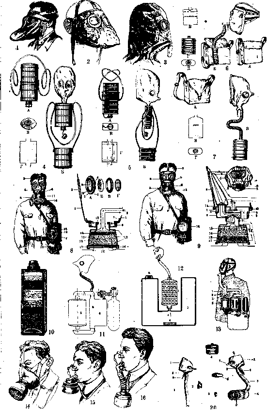
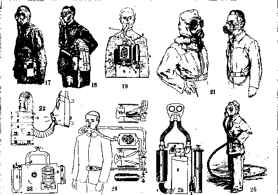
Fig. 1. Wet gas mask of the Chemical Committee. Fig. 2. French wet gas mask M2. Fig. 3. English wet gas mask-helmet PH. Fig. 4. Kumant-Zelinsky gas mask: A-gas mask in closed; B-in open form; C-view of box from below; D-section of box (without charcoal). Fig. 5. Gas mask of Avalov: A-in closed; B-in open form; C-view of box from below; D-schematic section of box (without charcoal). Fig. 6. English gas mask 1917-1918: A-gas mask in bag; B-in open form; C-section of box (without absorbent); D-gas mask box; E-view of box from below. Fig. 7. Gas mask TTS: A-gas mask in bag; B-without bag; C-section of box (without absorbent-filter); D-view of box from below. Fig. 8. German gas mask 1918: 1-leather mask; 2-elastic bands for securing the mask; 3-goggles: between the outer ring (a) and inner (b) are clamped: lens of celluloid (c), leather ring (d) and mask (1); B-anti-fog transparent celluloid plate covered with a layer of gelatin; C-inner metal ring attaching plate B to the end (b) by screwing; D-metal rim with crosspieces, screwed into ring B and protecting plate B from bulging when drying; 4-cord preventing the mask from inflating during breathing and thus reducing the 'dead space'; 5-tape for carrying the gas mask on the chest in 'ready' position; 6-wide metal 'mouth' ring; 7-leather ring; 8-metal ring securing the leather ring (7) and mask (1); 9-neck of the mouth ring (6) for screwing in the cartridge (11); 10-rubber washer for sealing the connection of the cartridge with the mouth ring; 11-cartridge (gas mask box); 12-bottom of the cartridge with holes for air passage; 13-grids; 14-chemical absorbent; 15-activated charcoal; 16-walls of the removable smoke filter; 17-smoke filter; 18-metal case; 19-case cover with compartment (z) for a packet with spare anti-fog plates; 20-canvas cover with spare cartridge; /-schematic path of inhaled, //-exhaled air. Fig. 9. French gas mask ARS: 1-mask; a-rubber half-mask for securing celluloid goggles in metal frames; 2 and b-bands for securing the mask; 3-tape for carrying the gas mask on the chest in 'ready' position; 4-fabric pouch supplying air to the goggles (to prevent fogging), with tape (e) sewn to the mask and supporting the pouch, and with metal device (g) securing the pouch in the valve box (5) with the help of brass tube (7), screwed into tube 9; 5-valve box; b-neck of the valve box for screwing in the cartridge; 7-brass tube screwed into another tube (8); 8-tubes for exhaled air; 9-exhaust rubber valve; 10-inhale rubber valve; 11-rubber washers for sealing; 12-bands securing the mask to the valve box; 13-cartridge (gas mask box); 14-metal grids; 15-cotton smoke filter; 16-activated charcoal; 17-chemical absorbent; 18-metal case. Fig. 10. Section of respiratory box of gas mask Barrere. Fig. 11. Diagram of isolating gas mask with oxygen supply from cylinder: 1-reducing valve with dosing oxygen supply by pressure; 2-cylinder with compressed oxygen; 3-cartridge for absorbing exhaled carbon dioxide; 4-breathing bag; 5-valve box. Fig. 12. Diagram of oxylite isolating gas mask: 1-oxylite cartridge; 2-breathing bag; 3-mouthpiece and nose clip; 4-wet sponge; 5-safety valve. Fig. 13. Filter-isolating gas mask: 1-switch; 2-exhaust valve; 3-inhale valve; 4-filter cartridge. Fig. 14-16. Masks of industrial gas mask. Fig. 17. Filter gas mask against CO of the German company Degesch. Fig. 18. Isolating gas mask Drager-Tuben. Fig. 19. Diagram of operation of Drager-Tuben apparatus. Fig. 20. Rubber helmet: 1-helmet; 2-tee; 3-ribbed tube; 4-box with filter-absorbent; 5-exhaust valve; 6-valve box protecting the valve from damage; 7-'nose' for wiping goggles; 8-inhale valve; 9-goggles. Fig. 21. Apparatus with air supply for protecting workers during pneumatic painting. Fig. 22. Diagram of absorbent of filter gas mask against CO of the German company Degesch: 1-drying mass; 2-active mass (catalyst); 3-indicator. Fig. 23. Diagram of self-rescuer Fesenko. Fig. 24. Diagram of isolating gas mask with constant (bottom) and automatically regulated (top) oxygen supply. Fig. 25. Diagram of apparatus producing oxygen: 1-absorbent cartridge; 2-oxygen producer (berthollet salt); 3-oxygen filter; 4-cooler; 5-breathing bag; 6-safety valve. Fig. 26. Hose self-sucking *
industrial gas mask.
a valve, which has the appearance of a tightly compressed rubber pouch with two slit-like openings for exhaled air, is placed on the lower branch of the T-shaped pipe. When inhaling, the walls of the valve collapse and prevent outside air from entering under the mask. To protect the exhalation valve from mechanical impacts, it is enclosed in a metal frame. The glasses, instead of the previous attachment with rubber stickers, are now inserted into metal frames. The glasses are made of thicker and better quality glass. - The gas mask is kept in a bag and worn on the left side. To protect the filling of the box from moisture when stored in warehouses, the lower opening of the box is sealed with parchment paper or closed with a cardboard plug. When the gas mask is issued, the paper or cardboard is torn. Gas masks currently used in the RKKA for training purposes have different markings depending on certain features of their design (e.g., TTS, BY) and number. Foreign dry filtering gas masks. The English and American gas masks of 1917-1918 (fig. 6), which are very similar to each other, had the same components as the one just described. The difference is the design of the face part in the form of a mask, which is tightly pressed to the face with straps. To wipe fogged glasses, folds of fabric are provided on the sides of the mask. In addition, compared to the T-shaped pipe, the design of the 'charcoal connector', connecting the corrugated tube with the mask, is different. For complete isolation of the respiratory tract from the air under the mask, a rubber mouthpiece is attached to the end of the charcoal connector that goes into the mask, which is inserted when using the gas mask into the mouth between the lips and gums. - To prevent breathing through the nose, the latter is compressed by a special clamp embedded inside the mask near the glasses. Such a design reduces the dead space to a minimum and allows normal use of the gas mask even if the mask is damaged. However, this also creates a number of inconveniences, namely: prolonged stay in such conditions causes fatigue, irritation from the mouthpiece causes increased salivation, the possibility of conversation is eliminated, and finally the nasal passages are excluded from the act of breathing. - The German gas mask of 1918 (fig. 8) consisted of a leather mask and a cartridge with an absorbent. The cartridge is screwed into the 'mouth ring' embedded in the mask. To combat fogging of the gas mask, it had celluloid plates covered with gelatin ('clarification plates') that had the ability to absorb moisture while remaining transparent. These plates were attached to the inside of the glasses with special metal rings. The gas mask did not have valves. - The French gas mask A US (Appareil Respiratoire Special) (fig. 9), which externally differs little from the German one, had a number of improvements. The main ones are: a) the 'mouth ring' was placed in the valve-distribution box, where the inhalation and exhalation valves were located; b) to combat fogging of the glasses inside the mask, there was a diaphragm, thanks to which the inhaled air, entering under the mask, flowed around the glasses and thus dried them. As for modern foreign gas masks, they differ little from the sample described above, adopted in the RKKA, except for the cut of the mask and somewhat different valve designs in some of them. - Filtering gas masks, providing reliable protection for several hours from all known chemical warfare agents, do not provide such protection from carbon monoxide. For work in an atmosphere containing this gas, either isolating gas masks or filtering ones with special filling are used. The latter consists of grains prepared from a mixture of freshly precipitated oxides of certain metals (manganese, copper, cobalt, silver), called 'hopcalite' and which is a catalyst, in the presence of which CO is oxidized to CO2. Isolating gas masks (oxygen apparatus) are used in cases where the surrounding atmosphere is poisoned by chemical warfare agents not absorbed by filtering gas masks (e.g., carbon monoxide), or at very high concentrations of chemical warfare agents when filtering gas masks do not completely purify the air, and finally for work in an atmosphere with low (or devoid of) oxygen content. The design of oxygen apparatus is such that they completely isolate the worker's respiratory organs from the external environment, while themselves serving as a source of the oxygen necessary for breathing, simultaneously absorbing the exhaled carbon dioxide. Depending on the method of delivering O2 and absorbing CO2, there are two types of isolating gas masks. In one, oxygen is contained in a highly compressed state (up to 150 atm.) in special cylinders, from which it enters the apparatus; for absorbing CO2, grains of caustic alkali placed in a separate cartridge are used. In the other, oxygen is released under the influence of exhaled moisture from potassium or sodium peroxide (otherwise oxylite) located in a special cartridge according to the equation: 2K2O2 + 2H2O = 4KOH + O2; carbon dioxide is absorbed by the caustic alkali (KOH, NaOH) formed in this process according to the equation: 2KOH + CO2 = K2CO3 + H2O. Both types consist of the following parts (figs. 10-13): a) mask or mouthpiece with a bitepiece (if a mouthpiece is present, the apparatus has a special nose clip and separate glasses, worn as needed); b) breathing bag, where oxygen enters, as well as exhaled air after its regeneration; to prevent rupture, the bag is equipped with a safety valve; c) connecting rubber tubes (one or two); d) oxygen cylinder with a reduction valve and a device regulating the supply of oxygen in the required amount, or an oxylite cartridge; e) regenerative cartridge with an absorbent for CO2; with an oxylite cartridge, an absorbent for carbon dioxide may not be present, however, some samples of oxylite apparatus have separate oxygen and CO2 absorption cartridges; f) in some apparatus there is a cooling device for cooling the inhaled air, which is heated both in the cartridge for CO2 absorption and in the oxylite one; g) in apparatus with compressed oxygen, there may be a so-called finimeter-manometer, which allows determining the pressure in the O2 cylinder and thus its amount at any given moment. When using the gas mask, exhaled air goes through the connecting tube first to the absorption cartridge, then, freed from carbon dioxide, it enters the breathing bag, mixing with oxygen either in the bag or on the way. From the bag, the regenerated air enters the respiratory organs through the second connecting tube or (in a design with one tube) through the same one through which exhalation occurred. The exhalation and inhalation valves in the gas mask allow air to move in only one direction. In less perfect apparatus, the movement of air is pendulum-like, similar to the movement in valveless filtering gas masks. The desire to prolong the operation of the oxygen apparatus led to the creation of a design combining a filtering gas mask with an isolating one (fig. 13). Normal breathing is done through a respiratory box of conventional design; in case of necessity, the latter is turned off by a lever, and the apparatus begins to operate on the oxygen type. Such filter-isolating gas masks are produced by the German firm Dräger. Factors affecting the body of the gas mask user. In addition to the negative aspects associated with working in a gas mask (restricted movement, the need for constant monitoring of its condition, awareness of the danger of the surrounding environment), the latter also has a number of shortcomings that affect the normal functions of the body to one degree or another. These include: a) increased resistance to breathing, depending on the density of the respiratory box filling and causing a violation of normal air pressure in the lungs and pleural space (this resistance in modern military gas masks, determined on a device that gives 30 liters of continuous air flow per minute, is approximately 30 mm of water column on inspiration and 8-10 mm on exhalation); b) the presence of dead space, leading to a change in the composition of the inhaled air and a violation of normal gas exchange; c) pressure of the helmet (mask) on the blood vessels as well as on the underlying nerves of the head; d) the presence of glasses embedded in the mask, which interfere with normal vision.
The aforementioned shortcomings are largely mitigated if the following rules are observed when using Gas Masks: a) breathe deeply, which reduces the influence of harmful spaces; b) breathe not often, calmly and evenly, since any sharp respiratory movements increase the resistance of the Gas Mask; c) in case of shortness of breath, increased breathing above 32 per minute, and a pulse above 140 beats—assume a resting position and try to calm the breathing; after this, the pulse usually calms down soon (during training, if the mentioned measure does not help—remove the Gas Mask); d) during training, increase the load gradually, moving to intensive work only after the first two rules (a, b) have been fully mastered; e) choose the helmet according to the size of the head, which is determined by the sum of measurements: the length of the circular line passing along the edge of the chin and along the cheeks through the highest point of the head, and the length of the line connecting the openings of both ears and passing through the eyebrow arches; the resulting value (in cm) gives indications of the required helmet size, namely up to 95 cm—size 1, from 95.5 to 99—size 2, from 99.5 to 103.5—size 3, from 104 and above—size 4. This method is correct only in 80-90%, and therefore requires additional fitting of the helmet; f) the negative influence of glasses, expressed in narrowing the field of vision, is reduced by bringing them closer to the eyes (correct wearing of the helmet); to combat fogging, in addition to the methods mentioned above, special lubricants are applied to the inner surface of the glasses, followed by wiping the glasses dry with a soft cloth.
A. Grigoriev.
Industrial gas masks (protective masks, respirators) have a fundamental difference from military gas masks: there is no need for them to have universal protective properties. It is quite sufficient for an industrial gas mask to provide protection only from the poisonous substances characteristic of a given production. This circumstance allows for a significant reduction in the weight and volume of the absorbent in industrial gas masks, and thus their construction can be limited to just a mask and a small respiratory box (cartridge). The latter, attaching to the mask in the same way as in the German gas mask, allows for cartridges with different contents to use the same mask (fig. 10). Among industrial gas masks, there are also those with considerable universality. For example, the American "Barrel-mask" device, intended for miners and firefighters, provides protection from chemical warfare agents in gaseous, foggy, and smoky states; at the same time, it also protects against CO. The device consists, like a military gas mask, of a mask, corrugated tube, and a respiratory box with an 8-layer filling. Certain types of these devices (isolating gas masks-"self-rescuers") ensure safety when working in conditions of insufficient oxygen content in the surrounding air. In each gas-hazardous industrial enterprise, industrial gas masks must be available in sufficient quantity and of proper quality. The correct choice of gas mask type, their rational storage, and periodic testing are of great importance. The main consumers of industrial gas masks are the chemical, metallurgical, and mining industries. The main difference in Soviet health improvement methods is the focus on the radical elimination of existing causes of gas release in production, and the use of industrial gas masks should in no case replace these measures. Industrial gas masks are mainly used in the following cases: a) in accidents associated with gas entering the workroom; b) during repair work, as well as cleaning of gas ducts, gas outlets, their valves, etc.; c) when descending into various gas-hazardous tanks, vats, wells, etc.; d) with temporary insufficiency of health improvement measures in the workshop. Industrial gas masks (of appropriate types) are widely used in mine rescue work; Existing industrial gas masks can be divided into three types: 1) filtering, 2) isolating, 3) hose. As the name itself shows, the basis of the action of industrial gas masks of the first group is the filtration of the inhaled air, i.e., its liberation from gaseous and vapor-forming industrial poisons.-Isolating gas masks completely isolate the worker's respiratory organs from the surrounding air, ensuring their proper oxygen supply through the oxygen reserve carried in the device or formed in it.-Hose industrial gas masks also isolate the respiratory organs from contact with the air directly surrounding the worker, allowing clean air to be obtained through a hose from an uncontaminated zone somewhat removed from the workplace.- The main indications and contraindications for the use of individual types of industrial gas masks are as follows. 1) Filtering gas masks can only be used provided there is sufficient oxygen content in the air (at least 15%) and only in the case that the industrial poison in the air corresponds to the one against which this type of filtering gas mask is intended. An excessively high concentration of this poison, as well as ignorance of the composition of the gas mixture in the air of workrooms, are contraindications for the use of filtering gas masks. 2) Isolating and hose gas masks are used in cases where the use of filtering gas masks is impossible. The main obstacles to the use of isolating gas masks can be: difficulties in working in a small workspace (inside gas ducts, etc.), with the relatively large dimensions of respiratory devices, and the mismatch between the required duration of work and the service life of the device (mainly there are devices of one-hour and two-hour duration).* An obstacle to the use of hose gas masks is the absence of an uncontaminated air zone near the workplace and the need for the worker to move during work (non-constancy of the workplace). Filtering industrial gas masks can be mono- and polyvalent. In the first case, they have specific protective properties against certain gases and vapors, in the second-against a series of industrial poisons. The first (with correct selection and use) provide more effective protection (longer duration, higher maximum gas concentration at which the gas mask can be used, etc.). Existing types of filtering industrial gas masks also differ in the principle of operation of the filters themselves. In some cases, the basis of the filtering action of the cartridge is the ability of certain substances to absorb (adsorb) gaseous and vapor impurities in the air; in others, there is a chemical interaction between the "chemical absorbent" and the aforementioned gaseous impurities, and finally, in the third, a catalyst causes the poisonous substance to be converted into a harmless one through its combination with other gases in the air or through its decomposition. In the first case, the filtering material is substances with a developed absorption surface (various granulations of activated carbon, etc.); in the second, these are specifically selected chemical reagents (for example, soda lime, used to neutralize so-called acidic gases; copper sulfate-for absorbing ammonia, etc.). In a number of types of industrial gas masks, the cartridge contains, along with activated carbon, a specific chemical absorbent. The earliest filtering industrial gas masks consisted of a primitive mask into which wet filters were placed: sponge or gauze soaked in some neutralizing solutions (acetic acid, lime waterg hypo sulfite, etc.). Modern industrial gas masks do not have such wet filters, which ensures their greater capacity, possibility of long-term storage, etc. The service life (capacity) of a filtering industrial gas mask cartridge depends on its size (rather, the size of the surface of the absorbing material), the physicochemical properties of the absorbent, as well as the conditions of use of the industrial gas mask in production (and primarily on the gas concentration in the air). Filter exhaustion does not occur instantly but happens gradually, and as a result, the worker using the gas mask can (by smell, taste, irritating effect) detect the beginning of the breakthrough of small amounts of gas. Filtering industrial gas masks produced by the Soviet Snabosovikhim were tested at the All-Union Central Institute of Economics, Organization, and Labor Hygiene, and the following capacity was established in relation to the main industrial poisons. Industrial poison Test concentration (mg per 1 liter) Time (min.) through which gas breakthrough was noted Retained by filter (in g) |- A Protective Benzene vapor 7-68-790 1-27.47-28.29 ; 1 » » » » 150-193 ! » » toluene 1(1 03- 9ci 27.87 -23.49 ! 1 * » » gasoline 80-115 26,7J -31.41 ! 1 » » » carbon disulfide 690-711 28.05 -30.66 i » !' * » aniline 450-475 62.61 -70.80 1 Б Yellow Sulfur dioxide 5.7 49- 50 8.57 - 9.12 » Hydrogen sulfide 0.75 46- 74 1,'0 - 2,5t ! * » Chlorine 8.0 35- 48 8.62 -10.92 : | K > Blue Ammonia 3.7 30- 41 4.51 - 7.25 The actual service life exceeds the indicated times by approximately two times, since under experimental conditions (continuous suction of gas through the filter) there was no natural alternation of inhalation and exhalation. In addition to the indicated types, Snabosovikhim produces industrial; gas masks against mercury vapors (the absorbent for which was developed at the Institute of Labor Protection) type "M", gray box. An example of a filtering gas mask, the absorbent of which contains a catalyst-oxidant, is the modern filtering industrial gas mask against CO. In it, with the help of a catalyst (hopcalite), CO is oxidized to CO2 through the oxygen in the air. The composition of hopcalite (one of the variants): MnO2-50%, CuO-30%, Co2O3-15%, Ag2O-5%... The peculiarity of CO as an industrial poison (lack of any smell or taste, as well as irritating effect) for a long time hindered the development of a filtering industrial gas mask against it (impossibility for the worker to determine the moment of filter exhaustion). At present, this problem has been solved in several ways. In American devices, a special breathing counter is installed, according to the readings of which the service life, and therefore the validity of the filter, is determined (the approximate duration of the catalyst's service life, which mainly loses its properties under the influence of moisture, is determined in advance when the industrial gas mask is issued). In German industrial gas masks of the Degesch company (fig. 17), the problem is solved differently: the moment of "exhaustion" of the filter is signaled by the release of a special pungent gas (acetylene), formed by the action of water vapor that has passed through the drying layers of the filter on a specially placed indicator-carbide-calcium (fig. 22) in the cartridge.
A third method for determining the 'exhaustion' of the filter is also possible: since each cartridge contains a drying layer designed to retain a certain amount of water vapor from the inhaled air, it is possible to judge the moment of use of the drying part of the filter, i.e., the onset of possible loss of activity by the catalyst, by the increase in the initial weight of the cartridge. Since the allowable weight gain is determined during the manufacture of the apparatus, the producer-consumer has the possibility, through regular weighing, to determine the degree of exhaustion of the cartridge. The maximum concentration of CO in the air at which these industrial gas masks can be used should not exceed 6%. This concentration is established on the basis that the oxygen content in the inhaled air should not be less than 12%: assuming that 6% CO displaces an equal amount of oxygen in the workroom air, and that the oxidation of this amount of CO consumes half the amount of oxygen (since 2CO + O2=2CO2), it is established that at this concentration the air actually received by the respiratory organs will contain 12% O2. The attachment of filters to the worker's respiratory organs can occur in various ways: by means of a mouthpiece, half-mask, mask, or helmet (Figs. 14-16). Industrial gas masks of Sobbso-aviakhim have a rubber helmet (Fig. 20). Industrial gas masks are generally equipped with inhalation and exhalation valves. Before use, the apparatus must be tested for the tightness of the mask's fit to the face, for the integrity of the masks themselves, the proper functioning of the valves, the non-exhaustion of the filters, etc. The storage of industrial gas masks must be properly organized (protection of the absorbent from gases, vapors, etc.).- Isolating industrial gas masks, mainly used in mine rescue work and to a lesser extent in the metallurgical and chemical industries, belong mainly to the so-called regenerative apparatus, i.e., those capable of freeing the exhaled air from impurities of water vapor and CO2 with the subsequent use of this purified air (by adding to it the required amount of oxygen). To this day, the principle established for such apparatus by Schwann in 1853 has remained fully valid, namely: 'The exhaled air must be purified of CO2 by means of some chemical reagent and, by the addition of O2, be converted again into air suitable for breathing.' In terms of the technical solution to the problem, the closest to modern are the Dräger apparatuses, produced in 1912. In subsequent years, the apparatuses received further technical improvements. At present, all existing types of regenerative isolating industrial gas masks can be reduced to two main groups: pneumatofores, in which the oxygen necessary for inhalation is supplied from oxygen cylinders carried in the apparatus, and pneumatogenes, in which the oxygen necessary for breathing is formed at the moment of consumption in the apparatus itself. In both types, the absorption of carbon dioxide and water vapor occurs in special cartridges (alkaline). The further classification of the first group of apparatuses is based on the features of individual types concerning the oxygen supply system. In accordance with this, there are apparatuses: with constant (non-adjustable) oxygen supply, with adjustable (automatic, manual, or mixed) supply, and with combined supply (i.e., with the possibility of adding oxygen to the constant supply). The question of the dosage of oxygen supplied by the apparatus is important because, with an increase in pulmonary ventilation during heavy work, there arises a need for a greater supply of oxygen by the apparatus. Apparatuses with constant oxygen supply are set to an oxygen inflow of 2 liters per minute (consumption, however, varies from 2/3 liter to 3 liters per minute, depending on the nature of the work). The principle of constant oxygen supply is irrational, as it shortens the possible duration of use of the apparatus (since the amount of oxygen consumed exceeds that necessary for breathing during light and moderate work, while during very heavy work it may be insufficient). Apparatuses with manual adjustment of oxygen supply include the Fesenko self-rescuer. The scheme of the apparatus is given in Fig. 23. The exhaled air passes through the mouthpiece 1 through an alkaline regenerative cartridge 2, placed inside the breathing bag, after which it enters the bag itself (made of rubberized fabric), where it mixes with oxygen supplied from cylinder 3 by means of valve 4, adjusted by hand. The air thus restored passes through valve 5, hose, and mouthpiece into the respiratory passages. The weight of the apparatus is 5.5 kg, the duration of operation is 1 hour. The Dräger-Tüben self-rescuer of 1924 (designed for 1/2-1 hour of operation) also belongs to this group of apparatuses. When using such apparatuses, special training and physical conditioning of the workers are necessary. The occupation of one hand (adjustment of supply) limits the worker's capacity for work. A representative of the group of apparatuses with combined oxygen supply is the Dräger-Tüben apparatus, model 1924 (Fig. 18). The scheme of operation is shown in Fig. 19. The exhaled air enters the distribution box 2 through hose 1, then into the alkaline cartridge 3; from there it goes into the breathing bag 4, where it mixes with oxygen coming from cylinder 5 through a reducing valve 6, designed to supply 1-2 liters per minute. The so-called 'finimeter' - an apparatus showing the degree of use of oxygen reserves - is also placed here. The apparatus weighs 7.5 kg. It is designed for 1 hour of continuous operation. Apparatuses of Dräger of 1928 and others also belong to this category. The scheme of the device for automatic adjustment of oxygen supply is shown in Fig. 24, where both variants are compared: with constant and automatic oxygen supply. The main disadvantages of this group of apparatuses - great technical complexity and great weight - cannot overshadow their advantages. In all the mentioned apparatuses, the freeing of the exhaled air from CO2 and water vapor occurs in cartridges consisting mainly of caustic soda and calcium hydroxide. The absorption itself occurs according to the following equations: 1) 2NaOH+CO2=Na2CO3+H2O + 28 kcal. 2) NaOH+H2O=(NaOH·H2O)+3.2 kcal. or Ca(OH)2+CO2=CaCO3+H2O. As can be seen from the above, heating of the air occurs during the regeneration process, in accordance with which the temperature of the air inhaled by the worker is increased. According to the data of Lewenz, the temperature inside the cartridge can reach 120°, while the temperature of the inhaled air (at the mouthpiece) does not exceed 40-43°.- The type of Soviet isolating industrial gas mask, the manufacture of which was first undertaken in 1932, was developed in various scientific and practical institutions of the Union (Makeevsky Institute of Labor, Stalin Mining Institute, etc.). The Safety Engineering Trust released the first batch of isolating industrial gas masks in 1933 under the brand 'KIP'. The complexity of all the mentioned apparatuses requires good training of the workers, as well as systematic checking of the condition of the apparatus (regenerative cartridge, breathing bag, valves, etc.) and checking the tightness of the entire apparatus as a whole. The main disadvantage of all the listed types of isolating industrial gas masks is their great weight, volume, and complexity of design. Therefore, any rationalization aimed at eliminating these shortcomings is especially appropriate. Pneumatogenes are those new types of industrial gas masks that do not have some of these disadvantages. The reduction in their weight is achieved by removing the heavy steel cylinders with compressed oxygen (at a pressure of 150 atm.) from the apparatus and replacing them with oxygen-generating cartridges. The first proposals in this direction were made in 1924 by Bamberger and Wenck. Some apparatuses of this type are capable of generating oxygen from solid chemicals under the action of exhaled water vapor and carbon dioxide. Such chemical production of oxygen is possible when using potassium and sodium peroxides (KNaO3) or sodium peroxide (Na2O2). The corresponding reactions proceed according to the following equations: in the first case: 1) KNaO3 + CO2=KNaCO3 + O2 + 54.1 kcal.; 2) KNaO3 + H2O=KOH + NaOH + O2 + 2.22 kcal.; in the second case: 1) Na2O2 + CO2=Na2CO3 + 1/2O2 + 55.8 kcal.; 2) Na2O2 + H2O=2NaOH + 1/2O2 + 27.8 kcal. In the latest apparatus of the Inhabad company, oxygen is generated from potassium chlorate under the action of a mechanical cause (similar to detonation) according to the following equation: KClO3=KCl + 3/2O2 + 9.8 kcal. In this apparatus, oxygen generation occurs continuously (independent of the action of CO2). The absorption of exhaled carbon dioxide here also occurs by means of alkaline cartridges (Fig. 25).
The operation of hose-type gas masks is based on the complete isolation of the respiratory organs from the surrounding workplace air, with the delivery of fresh air from a non-contaminated zone. The simplest type of such industrial gas mask is the self-inhalation apparatus (Figure 26). These devices consist of a rubber hose and a mask . The length of the hose is limited by the difficulty of inhaling air with the force of the respiratory muscles when the hose is long (more than 20 m is unacceptable). A filter is installed at the end of the hose to remove dust from the inhaled air. Another type of hose industrial gas mask is based on the supply of air from special devices (compressors, fans, injectors, bellows). In these devices, the hose can be longer. Devices of the same type include industrial gas masks proposed for the protection of workers during pneumatic painting (protection from the finest droplet suspension of paint and its solvent vapors). The device consists of a half-mask , into which fresh air is supplied through a hose from a rubber air hose used to operate the device - the paint sprayer.
3. Israel's.
Related articles
Mentioned in
Cite this page
“Gas Masks.” Soviet Medical Encyclopedia. English translation of Bolshaya Meditsinskaya Entsiklopediya, 1st ed. (Moscow, 1928–1936), ed. N. A. Semashko. https://sovietmedicalencyclopedia.pages.dev/article/gas-masks/