Projection Apparatus
Historical document, translated for reference. It reflects medical knowledge of the 1920s–30s and is not medical advice.
Summary
This article describes various types of projection apparatus used in medical and scientific demonstrations, including shadow projectors, diascope projectors, episcopes, and projection microscopes, with details on their construction, operation, and applications.
Encyclopedia article (1928–1936)
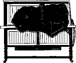
PROJECTION APPARATUS, apparatus with the help of which an image is obtained on a screen. The simplest method of projecting various objects onto a screen is shadow projection. The screen is illuminated by a beam of diverging rays from a powerful light source. Objects are placed in the path of the light rays, from which shadows are cast onto the screen. The light source should be taken as point-like as possible (for example, a voltaic arc) to avoid the phenomenon of half-shadows. In shadow projection, no optical glasses should be used under any circumstances. Shadow projection is especially frequently used when demonstrating various experiments in large lecture halls. In Fig. 1 is given an example of demonstrating a siphon in shadow projection. (On the right is a bomb with CO2, with a reducing valve and a rubber tube for filling the upper glass.) For shadow projection, one can use an ordinary projection apparatus with a voltaic arc, removing the condenser and objective. The liliput lamp (with a voltaic arc) is even more convenient for shadow projection.
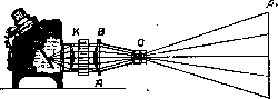
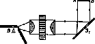
For ordinary projections in transmitted light (diascopic projection), projection lanterns are used. In such a lantern (Fig. 2), between the light source and the object to be projected, a biconvex lens (or better two plano-convex lenses with their convex sides facing each other), the so-called condenser, is placed, the purpose of which is to collect the diverging rays of the light source and thereby more strongly illuminate the object (AB), which is placed between the focal and double focal distance of the objective (O). A real enlarged image (A1B1) of the object is obtained on the screen. The focal distance required for clear projection is established with the help of a rack that moves the objective frame, as well as by adjusting the light. To obtain a correct image of a slide on the screen, it should be placed in the projection apparatus upside down 1) 'head down' and 2) with the front side toward the screen. When projecting experiments, it is of course highly undesirable to obtain inverted images on the screen, for example, so that liquid flows from bottom to top. Therefore, it is necessary to reverse the path of the rays to the screen beforehand. This is achieved by passing them through a reversing prism (see the diagram in Fig. 3), placed after the objective in the narrowest part of the beam of rays.
In diascopic projection lanterns, the light source is usually a voltaic arc, and in cheaper ones, a powerful electric lamp is often used instead. The disadvantage of lanterns with lamps is the uneven illumination of the object being projected. Acetylene lamps are also used. In prerevolutionary years, alcohol lamps were widely used. In the absence of these light sources (in rural conditions), a kerosene lamp with a flat wick can be used. Skill in handling the light source is extremely important, as usually malfunctions with the light source cause many difficulties during illustration. In projection apparatus, the voltaic arc is equipped with either an automatic or a manual regulator. Manual regulation is preferable, allowing more precise setting and subsequent maintenance of the position of the voltaic arc, which proves to be absolutely necessary when projecting a series of experiments. In projection apparatus for projecting slides, an arc with automatic regulation is more convenient. When using an arc powered by direct current, a manual regulator should be used, in which the positive carbon is positioned horizontally, and the negative one either vertically or somewhat inclined. With this arrangement of carbons, the blocking of the crater of the arc, which is its brightest part, by the negative carbon in the horizontal direction is avoided, which is very important for projection apparatus. To protect the condenser from carbon fragments from the voltaic arc, it is recommended to place an ordinary window glass between the condenser and the voltaic arc. To avoid heating the objects being projected in projection apparatus with a voltaic arc, the light rays are made to pass first through a plane-parallel water bath, placed either between the condenser lenses or directly behind it. The bath should be filled with distilled water, as tap water contains air, which is released in the form of bubbles settling on the walls of the bath and reducing the brightness of illumination.
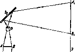
In slide projection apparatus, the objective is attached directly to the lantern, while in projection apparatus for demonstrating various experiments, the objective is separated from the lantern body and mounted on a separate tripod. For projecting slides, as projection apparatus, one can use an ordinary photographic camera. The back wall of the camera is removed and a slide is placed in a special frame in place of the cassette. To illuminate the slide, a lighting lantern is attached to the camera, in which a powerful electric bulb is placed at the focus of a concave mirror (spherical or preferably parabolic). The objective of the camera serves as the lens. A similar setup is also used for enlarging photographs. In the latter case, a negative is placed in a frame in place of the cassette, and photographic paper is fixed in place of the screen. Many experiments can only be performed in horizontal vessels. For projecting them onto a vertical screen, a very simple device is used - the horizontal projector (Fig. 4). The light rays from an ordinary projection lantern, after the condenser, fall on a flat mirror 31, set at an angle of 45°, and illuminate the horizontal object AB. Further, the rays enter the objective O, which can move in the vertical direction, then fall again on a second flat mirror 32, also set at an angle of 45°, and, after reflecting from it, fall on the screen, where the image A1B1 is obtained. In horizontal projectors, mirrors 31 and 32, the objective, and the table with a glass bottom for the object AB are usually mounted together on one tripod. Often instead of mirror 32, a prism with total internal reflection is used.
For projecting opaque objects - drawings, pictures, photographs - reflective projection apparatus - episcopes - are used. In them, the light rays, after reflecting from a mirror, fall on the object to be projected, reflect from it, and their further path is the same as from the table of the horizontal projector. Most episcopes are adapted for slide projection as well, and then they are called epidiascopes (Fig. 5). The best epidiascopes are made by Zeiss in Germany and Reichert in Austria.
For demonstrations in medicine, physiology, physics, mineralogy, and chemistry, it is very important to be able to use microprojection. For this purpose, projection microscopes are constructed. A flat mirror at a 45° angle is attached to the microscope at the eyepiece, and with its help the image is projected onto a screen, by selecting the appropriate focusing. Special illuminators are used as the light source, mounted near the lower concave mirror of the microscope. One can also use the light from an ordinary projection lantern (in a convergent beam of rays), but in this case it is absolutely necessary to weaken the thermal effect of the rays by passing them beforehand through a thick layer of water (through 2-3 water baths) (see Microscope, Fig. 56). For projection onto a vertical screen, any microscope can be adapted by placing a prism with total internal reflection (or a flat mirror at a 45° angle) above the eyepiece. A projection microscope with a mirror can be very simply adapted for projection onto a horizontal plane, which is very useful for work related to drawing specimens.


a. Iris. Projection apparatus are one of the most common means of applying the visual method (see), making any visual aid, even of small size, accessible to a large audience. The projection lantern was invented in the late 16th, early 17th century. First described by Kircher ("Ars magna lucis et umbrae", 1671). The importance of the projection lantern, which was widely used in the early 20th century, is now declining in connection with the development of cinematography, which due to its dynamism has exceptional advantages over static projection, making it possible to show much more clearly various physiological or pathological processes (e.g., blood circulation, movement, digestion), as well as production processes from the point of view of labor hygiene, first aid training (bandaging), etc. Lantern slides ("hazy pictures") are glass plates measuring 87a X81/* cm (abroad the size 10x87g cm is accepted), on which some image, drawing is applied. Usually lantern slides are made in the same way as photographs, by placing a positive plate instead of photographic paper on the negative and passing light rays through it. For durability, the lantern slide is covered with a simple cover glass and edged with black paper around the edges. The black lantern slides obtained in this way can be painted with aniline transparent paints; since small drawings are usually painted by hand, this doubles (and sometimes more) the cost of the lantern slides. Along with the most common production of lantern slides photographically, they can also be made by drawing ordinary glass with ink (black or colored), in this way cartoons, slogans on glass can be made. To make such homemade lantern slides, cut glass is coated with a composition of gelatin, and on such glass, which has a slightly rough surface, a drawing is easily applied. Lantern slides are inserted into the lantern with the help of a special wooden frame, usually designed for 2-3 lantern slides, with a movable socket that allows the lecturer to change lantern slides without interruption. The lantern slide is inserted into the frame upside down, with the top part down, because reverse projection is obtained. For safe transportation of lantern slides, special boxes with sockets are made. However, a set of 50 glass plates weighs quite a lot and is bulky. Therefore, in recent years, the production of lantern slides on film has become widespread, where on a small reel, convenient for carrying in a pocket, 30-40 lantern slides can be placed. A significant saving is obtained in price, since a black lantern slide costs 40-50 kopecks, while a reel with 40 lantern slides on film costs only 80 kopecks, i.e. 20-25 times cheaper. Unfortunately, these film lantern slides cannot be projected on an ordinary lantern and require either changing the lens or a special apparatus, which is now produced under the name "filmoscope". Lantern slides can be used for the so-called "light newspaper", where a certain topic is presented on lantern slides in sufficient sequence with connecting texts, special cartoons, etc. Screen for receiving the enlarged image. Any smooth white surface (plastered whitewashed wall, sheet of paper) can be used as a screen, but in such cases, of course, it is difficult to obtain a completely clear image. Usually the screen is made of canvas, and movable screens are fixed on poles. The standard size of the screen is 2x2 m, 2.5X2.5 m. a. Edelstein.
Related articles
Mentioned in
Cite this page
“Projection Apparatus.” Soviet Medical Encyclopedia. English translation of Bolshaya Meditsinskaya Entsiklopediya, 1st ed. (Moscow, 1928–1936), ed. N. A. Semashko. https://sovietmedicalencyclopedia.pages.dev/article/projection-apparatus/