Microscope
Historical document, translated for reference. It reflects medical knowledge of the 1920s–30s and is not medical advice.
Summary
This article from the 1928–1936 Soviet Great Medical Encyclopedia provides a historical overview of the development of the microscope, from early simple magnifying glasses to the compound optical systems of the 19th and early 20th centuries. It details the contributions of figures like Leeuwenhoek, Hooke, and Abbe, and describes the various types of magnifying glasses and microscopes used for scientific and medical research.
Encyclopedia article (1928–1936)
MICROSCOPE (from the Greek mikros—small and skopeo—I look), an optical instrument for studying small objects inaccessible to direct observation by the naked eye. A distinction is made between a simple microscope, or magnifying glass, and a compound microscope, or microscope in the proper sense. A magnifying glass is usually used for a coarser study of small details and provides relatively small magnifications (direct virtual images); a compound microscope is used for a more delicate study of structural details and provides an inverted, magnified, and virtual image, which is composed of two moments: the magnification of the front optical system of the microscope—the objective, which provides an inverted, real, magnified image, and the magnification of the second system—the eyepiece, which provides a magnified, direct, virtual image. Modern types of microscopes are the result of a long process of improvement of both the optical and mechanical parts of the instrument. History of the microscope. The art of manufacturing optical glass is connected with the grinding of stones, known since very ancient times. The first information about the use of optical glass also dates back to deep antiquity, and even in the excavations of Nineveh, indications of the use of biconvex collecting lenses made of rock crystal have been found. The property of biconvex lenses to magnify objects was also known to the ancient Greeks and Romans.

lib

Figure 1.
Figure 2.
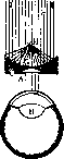
Figure 1. A—plano-convex lens; C—diaphragm; E—object under study; G—opening in the concave mirror; H—eye; I—parallel rays. Pliny also has information about the use of such optical glass, but their general distribution and systematic study date back to the beginning of the 13th century, when biconvex or plano-convex glass began to be used as reading glasses and spectacles. For actual microscopic purposes, optical glass began to be used from the end of the 16th and the beginning of the 17th centuries. The first microscopes consisted of a single biconvex glass.
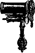
and therefore represented a simple microscope (magnifying glass). Such a glass was inserted into a frame and, for illumination purposes, was connected to a concave mirror or another collecting lens that concentrated light on the object under study. Among such first microscopes, one should mention the first microscope of Descartes (Fig. 1), the Zanonian flea glass, and the Ledermüller microscope, which represent a single glass in a tube-shaped frame, with the latter model already having a device in the form of a screw for more or less coarse focusing. A further improvement and complication of such a microscope are the microscopes of the Dutch self-taught scientist Leeuwenhoek, in which (Fig. 2) there is a device for securing the object and moving it by means of a screw, and the microscopes of Wilson, Lieberkühn, and Joblot, equipped with a stand or a handle for holding the instrument and an illuminating glass for concentrating light (Figure 3).
Fig. 3.
The first microscopists manufactured their own glass, and some of them, such as Leeuwenhoek, achieved great skill in this regard, as evidenced by the drawings of Leeuwenhoek, who discovered a number of microorganisms, seminal threads, etc. However, the first microscopes, despite the fact that a whole series of discoveries were made with them, had so many shortcomings that they did not become widely used. Their main drawbacks were the presence of spherical and chromatic aberration, which greatly spoiled the resulting image, although the magnification provided by such microscopes reached hundreds of times. Microscopes took their true place as a serious scientific instrument only from the beginning of the 19th century, when, as a result of the work of a number of physicists (Fraunhofer, Amici, and others) and technicians, designers of microscopes, complex optical systems were introduced into use—combinations of two or more glasses of different types, which made it possible to eliminate spherical aberration. At the present time, complex glasses (systems) that provide small magnifications are used exclusively as simple microscopes (Fig. 4). A compound microscope, which is a combination of two optical systems: an objective—the glass facing the object under study, and an eyepiece—the glass facing the researcher's eye, was proposed in 1590 by Hans and Zacharias Janssen from Middelburg in Holland. In the Janssen microscope
both the objective and the eyepiece were simple biconvex lenses. Representing a combination of two simple optical glasses (Fig. 5), this microscope, of course, further aggravated the shortcomings of the simple microscope, since the imperfect image of the objective was viewed through an equally imperfect eyepiece. In 1665, Hooke proposed a combination of two collecting lenses as an eyepiece, thereby laying the foundation for the design of modern eyepieces. In the second half of the 18th century, Euler calculated the first achromatic objective, built and improved by Martin in 1759 and then by Delle in 1807. It is not surprising that most researchers preferred the simple microscope, and the MIC

Objective. Eyepiece. Figure 4. Aplanatic magnifying glass. Figure 5. Microscope (compound) could not take its proper place until the beginning of the 19th century, when its improvement proceeded with rapid strides. In 1811, the work of Fraunhofer, in 1816—Amici, and finally Selligue, who calculated a compound objective executed by the famous French optician Chevalier (1824), improved the optical parts of the microscope to such an extent that there could no longer be any question of the previous skeptical attitude towards it. The design of the correction mount (Ross; 1839), the use of an immersion medium [first water, and then cedar oil
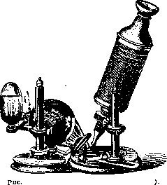
6. Microscope of Robert Hooke (1665).
homogeneous immersion (Abbe; 1878)] and finally the construction of the apochromat (Abbe; 1886) are the most important stages in the development of the microscope. At the present time, for the delicate study of details inaccessible to the naked eye, a compound microscope is used exclusively, to which the name "microscope in the proper sense" has been assigned. The first compound microscopes were very clumsy and inconvenient to handle, as can be seen from a number of the attached drawings (Figs. 6, 7, 8, 9, and 10). Only gradually did the external appearance of the microscope that is currently generally accepted develop. Simple microscope (magnifying glass). Magnifying glasses are currently used when working with objects that stand on the border of macroscopic and microscopic study (macro-microscopy). They are of particular importance when manipulating small objects (experimental embryology, dissection of very thin vessels and nerves, etc.). Magnifying glasses, according to their purpose, are manufactured in various frames and consist of
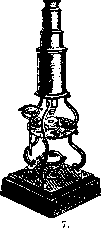
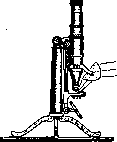
Fig.
Figure 8. Figure Microscope of Culpeper and Scarlett (1750). Figure 8. Microscope of Selligue and Chevalier (1824). One or more achromatic lenses, arranged so that their common focus is always greater than the distance between the individual members of the magnifying glass. A magnifying glass must have a sufficiently large field of view and good correction so that sharp contours are obtained. Among the most commonly used types of magnifying glasses, the following should be mentioned: 1. Handheld magnifying glass. It consists of an achromatic pair in a frame with a hinge, thanks to which it folds and fits conveniently in a pocket. Often 2-3 magnifying glasses are inserted into one frame, which can be used either
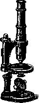
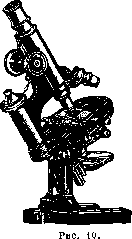
Figure 9.
Figure 9. Microscope of Chevalier (circa 1850). Figure 10. Microscope of Zeiss (1895). Singly or in combination, since when extended, it is centered thanks to notches on the frame (Fig. 11). 2. Magnifying glasses for optical setups have a short focus and are enclosed in a frame in which they can be fixed in a certain position, with their frame being tightly set on the glass. The magnification provided by them ranges from 6 to 10 times. They are used for focusing in photomicrography (Fig. 12). 3. Dissecting magnifying glasses—achromatic magnifying glasses of various powers made of one or more pairs, inserted into the socket of a corresponding stand, which can be very different. In its simplest form, this is a ring,
mi containing the magnifying glass with a handle, connecting

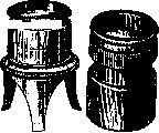
Figure 11.
Figure 12.
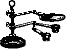
Figure 13.
connected by a ball joint to a heavy base equipped with a vertical column with a rack and pinion for focusing. More complex dissecting magnifiers have the appearance of a microscope stage with a glass mirror plate, under which an opaque, half-white, half-black plate is placed on a hinge, serving as a background for the objective. A mirror is placed under the stage, one side of which is made matte for dissection in transmitted light. Often, a collecting lens is located on an auxiliary stand for illuminating the specimen from above. To obtain different magnifications, a set of magnifiers with different focal lengths is provided with the stand (Figs. 13 and 14). 4. A demonstration magnifier on a stand in the form of a plate with a handle; a ring for magnifiers magnifying from 6 to 30 times is attached to a small pillar, and under the magnifier there is a round hole and 2 clips for holding the specimen. The magnifier with the specimen can be passed around the auditorium for viewing the specimen in transmitted light (Fig. 15). 5. Large plano-convex lenses with or without a frame are used as reading magnifiers. Price lists often include monocular and binocular microscopes (see below) among dissecting magnifiers, as well as magnifier-spectacles, which are uniquely constructed binoculars, i.e., telescopes with prisms. Such dissecting magnifier-spectacles, which require working with very small objects, have been released by the Zeiss firm and are successfully used in various types of operations.
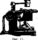
Description of the modern microscope. In a complex microscope, one distinguishes between mechanical parts and optics, which include the objective, eyepiece, and condenser. Mechanical parts of the microscope: a column with a specimen stage attached to it; a tube capable of moving up and down, and an illumination device with a diaphragm. The microscope column is attached to a heavy, usually horseshoe-shaped base, which gives the entire microscope the necessary stability. The lower, stationary part of the microscope column is attached to the base, having the shape of a cylinder, and more recently, a prism with a slot for housing the rod to which the mechanical parts of the illumination device are attached. The stationary part of the column is usually connected to the upper, movable part by means of a hinge, which makes it possible to tilt the upper part of the microscope up to a right angle, whereby the microscope tube assumes a horizontal position. By means of a screw with a handle, the hinge can be fixed in any position quite firmly. Such a hinge is absent only in the cheapest models.
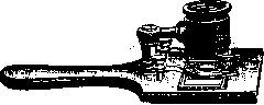
Figure 15
The upper, movable part of the microscope column is constructed in two ways: in older models, it represents a triangular prism, along which a cylindrical part with a corresponding groove along the axis moves, supported by a spring; by means of a crossbar, the spring is held at a certain tension and tends to lift the outer part of the movable part of the column with the tube attached to it; at the top of the movable part is a micrometric screw with a specific pitch, which makes it possible, when its head is rotated, to smoothly and slowly lower the microscope tube when tightening, and to raise it when releasing the screw due to the action of the expanding spring. In the newest models of the microscope, the upper part of the column, connected by a hinge to the lower one, is also made stationary and can serve as a handle for carrying the microscope from place to place; on the front side of this part of the column, in a corresponding cutout, a horizontal micrometric screw is placed, which rotates a obliquely cut cylinder, along which a small wheel connected to the microscope tube moves, which is pressed downwards by a spring; such a device of the micrometric screw ensures its greater durability and allows for finer movements of the tube, which is important at high magnifications (Fig. 16). In some cases, in cheaper models, the micrometric screw moves a small steel ball along an inclined surface, which is in contact with the tube support, which lowers due to its own weight, and can be raised by the ball; such a screw is significantly cheaper, but often causes stops when lowering the tube due to the friction of the ball against the inclined plane and the thickening of the lubricant. The head of the micrometric screw is made large in the form of a low cone or (in a horizontal screw) in the form of a cylinder and is divided along its circumference into divisions, making it possible, knowing the pitch of the micrometric screw, to determine the excursion of the microscope tube when the screw is turned by a certain number of degrees; usually, a scale of the screw head divisions is engraved on the head. Such a device makes it possible to perform vertical measurements under a microscope when setting
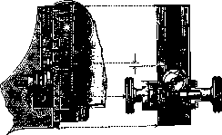
Figure 16. Micrometric screw with infinite travel.
the focus on the upper and lower surface of the object being studied or on its various elements located in different planes. For coarse adjustment, the tube is connected by means of a rack and pinion, which makes it possible, independently of the micrometric screw, to raise and lower the microscope tube over significant distances. Such a rack and pinion is now arranged in almost all models, and only old models or the cheapest school microscopes are devoid of it. In them, the tube is moved directly by hand and held in place due to friction between the outer and inner segments of the tube. Above the lower, stationary part of the column, above the hinge, the specimen stage is attached to the microscope column (almost always rigidly); only in models specially adapted for research in incident light and for photomicrography is the specimen stage connected by means of a rack and pinion to the lower part of the movable section of the column and can be raised and lowered. In the middle of the specimen stage, corresponding to the optical axis of the tube, there is an opening large enough to pass light and accommodate the illumination apparatus. The shape of the specimen stage and its size vary. In cheaper models, the stage is made quadrangular and completely stationary; in more expensive models, the stage is made round and can be moved by a few mm by means of screws in two mutually perpendicular directions, and also rotated around the axis of the microscope, which is very important when used for studying polarized light. The most perfect movable stage should be considered the large cross-shaped movable stage, which is arranged very precisely by most firms. On the disc-shaped base of such a stage, slides are arranged, along which, by means of a rack and pinion and a screw, the upper part of the stage can be moved in two mutually perpendicular directions. The movement of the stage in one direction or the other can be noted by means of a vernier. Such a stage makes it possible to systematically examine the entire specimen field by field, and also, by recording the divisions of the corresponding verniers, to mark a specific place in the specimen for a given microscope and then easily find it again. On the rack and pinion of the stage, there is a clamp-arrester, which makes it possible to turn the stage into a stationary one. The circular movement of the upper part of the specimen stage can also be stopped in a certain position by means of a screw. In some models, the edge of the upper disc of the movable stage is provided with degree divisions (important when using polarization instruments). The conveniences of a large cross-shaped specimen stage can be replaced in cheaper models by the use of an attachable cross-shaped stage (Fig. 17). An objective screw micrometer is a movable stage with a micrometric screw, allowing it to be moved with the specimen from left to right and back. On the head of the screw, there are divisions showing how much the stage has moved. A revolution counter is connected to the screw, which makes it possible to measure relatively large objects. The microscope tube usually consists of two parts that slide into each other; the outer, wider tube is connected to the rack and pinion and the micrometric screw, and the inner, narrower one moves freely inside the outer one and is held in place by friction. On the wall of the inner tube, divisions are usually marked, indicating the total length of the entire tube in mm, which is very important when using objectives from different factories corrected for different tube lengths. Some factories at the present time even provide expensive microscope models with a non-extendable tube, which makes it impossible to correctly use objectives from other firms with correction for a different tube length. The length of the tube is determined by the distance from the lower edge of the outer tube to the upper edge of the inner tube, on which the eyepiece rests with its flanges. The lower end of the inner tube is provided with a screw thread for screwing in the so-called internal microscope (see below). The microscope eyepiece enters the upper end of the inner tube freely, held by the flanges of the frame. At the lower * By optical, or reduced tube, one often understands the distance from the upper focus of the objective to the lower focus of the eyepiece.
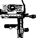
Figure 17.
At the end of the outer tube there is a screw thread for screwing on objectives or devices for changing objectives: a nosepiece or a sliding apparatus. The inner surface of both tubes is blackened to avoid the formation of light reflections. Screwing and unscrewing an objective from the microscope tube is troublesome, always significantly disturbs the setting, and takes quite a lot of time; therefore, for the most part, nosepieces for two, three, or four objectives or sliding apparatuses for changing objectives are used. The nosepiece consists of an upper solid plate with a protrusion equipped with a screw thread, by means of which it is screwed to the lower part of the microscope tube; a rotating disk with sockets for screwing in the objectives is attached to the upper plate on an axis. For centering the objectives when changing them, there is a notch on the back of the rotating disk of the nosepiece, into which a spring catch attached to the upper disk enters: when the catch coincides with the notch, the objective is centered. Since the nosepiece has a height of about 15 mm, when using it, it is necessary to shorten the optical tube accordingly; when using objectives from the same manufacturer as the stand, the microscope tube can remain at rest, and when changing objectives, one only has to correct the focusing using the micrometric screw; when using objectives from different manufacturers, it is necessary to raise the tube and perform the entire setup anew. The sliding apparatus consists of two parts that slide into one another; the upper part, equipped with cutouts, is screwed to the lower part of the tube, and the lower part of the apparatus serves for screwing in the objective; for centering, there are screws with a small key, by the rotation of which the coincidence of the optical axis of the objective with the optical axis of the microscope can be achieved. For each objective, there must be its own separate lower part (slide), centered for it; for storing such objectives with slides, boxes with sockets into which the slides slide are very convenient (Fig. 18). In the latest Leitz price lists, a device in the form of tongs with a spring is proposed for the same purpose; the objective is inserted into the lower branch of the apparatus, and the change of systems occurs very quickly. A device for housing the lighting apparatus is attached to the lower part of the stage. The simplest lighting apparatus is a mirror having two surfaces: flat and concave; a socket for diaphragms (cylindrical or plate) or a disk with round holes of different sizes, mounted on an axis so that the hole is located exactly on the axis of the microscope, which is noted by the clicking of a spring, is attached to the lower surface of the stage. In the latest models, even cheap ones, the illumination of the microscope is produced by an Abbe lighting apparatus, more or less complex, which is why small, medium, and large lighting apparatuses are distinguished. The entire lighting apparatus is attached to the microscope stage on a rod and moves up and down by means of a screw or a rack and pinion (the latter is more convenient), and the axis of the apparatus, coinciding with the axis of the entire microscope, does not shift to the sides. In the upper part of the apparatus, a ring is fixed into which the illuminator enters, and below it is the diaphragm. In cheap models that do not have a condenser, plate or cylindrical diaphragms are placed in this ring. In more expensive models, the diaphragm is always an iris one. It is arranged in such a way that crescent-shaped metal sectors move freely in a low drum; when moving the diaphragm handle, they are positioned either parallel to the circumference of the drum or become at an angle to the radii; in the first
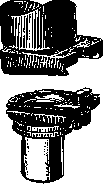
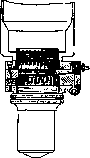
Figure 18.
case, the entire aperture of the condenser opens; in the second, due to the overlapping of the edges of the sectors, an opening of a larger or smaller size remains in the middle, which can narrow down to its complete closure. Such an iris diaphragm (pupillary) is very convenient to use and makes it possible to easily regulate the amount of light depending on the qualities of the specimen, the purpose of the study, and the individual characteristics of the researcher. In large illuminators, the iris diaphragm can be set more or less eccentrically by means of a gear, can rotate around a vertical axis, and can be completely moved to the side. At the lower end of the rod, in a fork-shaped frame, a mirror is placed, concave on one side and flat on the other; the mirror can rotate around mutually perpendicular axes and, without changing the position of the microscope, can be aimed at any light source in front of and to the side of the researcher. A condenser (illuminator) is inserted into the sleeve of the upper part of the lighting apparatus, which is a combination of two or three simple or achromatic collecting lenses; depending on the number of members of the system, its aperture (see below) can be different: from 1 to 1.4. The upper lens of the illuminator is made plano-convex and is installed with its flat side at the level of the upper surface of the stage or slightly lower; the focal length of the illuminator is calculated so that parallel rays of light are converged by the condenser at a distance equal to the thickness of a standard slide. In this way, the brightest illumination is achieved; by means of the above-mentioned rack and pinion, the apparatus can be raised and lowered,
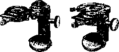
Figure 19. Abbe apparatus: a—with insertable condenser; b—with centering slides for Z-condenser.
In some models, the illuminator can be moved slightly to the sides by means of three screws for centering along the axis of the microscope (Fig. 19). In expensive microscopes, the condenser is placed in a special frame, by means of which it
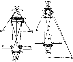
Figure 20. a—Diagram of the path of rays in a compound microscope: Obj—objective; Oc—ocular; B1B2—aperture of the objective diaphragm; E1E2—virtual image of the objective diaphragm (entrance pupil); F1 and F2—principal focal points of the objective; F'1 and F'2—principal focal points of the ocular; P1P2—object; P1'P2'—image of the object (magnified, real, inverted) produced by the objective; P1'' and P2''—image produced by the ocular (magnified, virtual, erect); AA—exit pupil of the microscope (Ramsden disk); b—change in the position of the final image of the object depending on the movement of the microscope tube in relation to the object: P1 and P2—object; P1''—image located at the distance of distinct vision (250 mm); P2''—image at a distance less than 250 mm—it is smaller. (Difference for an emmetrope and a myope.)
a swing-out condenser can be moved to the side, which is undoubtedly convenient when using very weak systems that have a large field of view exceeding that of the illuminator. Unfortunately, however, this swing-out device is very delicate and often breaks. Sometimes a weak objective is used as a condenser with the help of a special adapter part inserted into the sleeve in place of the condenser and equipped with a system of screws for centering, which disrupts the centering. Recently, the firm of Carl Zeiss has released microscopes (FZ) that make it possible, with the help of a sliding device, to change the illuminator in the same way that objectives are changed, which gives the researcher the ability to use both ordinary illuminators of different apertures and special ones, e.g., illuminators that provide a dark field of view, polarizers, etc.
Optical parts of the microscope. Among the optical parts of the microscope, the main attention should be paid to the objective, since the eyepiece plays only an auxiliary role, giving the opportunity to examine what is provided by the objective and not introducing anything new (Fig. 20).
Image formation and the path of rays in the objective. Rays emerging from a luminous point on the optical axis, after refraction in optical glass, will converge (image of the point) also on the axis at a specific point, at the conjugate focus of the optical glass (collecting lens); luminous points lying not on the optical axis give an image in a plane perpendicular to the optical axis and passing through the conjugate focus, the so-called focal plane. Thus, a luminous object lying on one side of the optical glass is copied point by point on the other side of it. In this case, rays coming from a very distant object draw it in the plane passing through the principal focus, in a reduced form.
As the object approaches the optical glass, its image increases. When the distance of the object is equal to twice the focal length of the glass, it is copied in natural size at the same distance. With further approach of the object to the glass, its image moves beyond the limits of the double focal length and rapidly increases.
When the object reaches the principal focus of the glass, its image goes to infinity, and upon further approach, the rays no longer cross but diverge, and an image of the object is not obtained, but it can be perceived by the eye and appears magnified and upright, lying on the same side as the object, whereas a real image is inverted: upper points are drawn at the bottom, left to the right, etc. (Fig. 21).
A real image can be received on a screen, and in it, each point of the object corresponds to one point of the image; but this takes place only if the points of the object lie close to the axis of the glass, only its central part is working, and the light consists of homogeneous rays.
When light passes through the marginal zones of the glass, the rays are refracted more strongly, and on the screen, a point of the object corresponds not to one point of the image, but to a series of points located along the axis—the phenomenon of so-called spherical aberration is obtained; likewise, with mixed light, rays of different wavelengths, refracting differently, will give a series of images of different colors: violet closer, red further—the phenomenon of chromatic aberration is obtained (Fig. 22).
When receiving an image on a screen, in the presence of spherical and chromatic aberration, we will not be able to obtain a sharp image at any position of the screen: circles of light diffusion, overlapping each other, will spoil the contours of the drawing and distort the image.
Spherical aberration can be quite easily eliminated by a corresponding change in the curvature of the peripheral part of the optical glass, and even better by combining glasses with different curvature, so that all rays will be brought to one point.
The elimination of chromatic aberration is associated with much greater difficulties. A method for eliminating chromatic aberration is the construction of a complex optical system composed of different types of glass. Different types of glass, as well as other transparent solid media, such as quartz or rock crystal, differ not only in different refractive indices but also in different dispersive power in relation to a mixed ray—the angle of divergence of rays of different colors after their refraction turns out to be different and does not correspond to the difference in refractive indices.
By arranging combinations of different types of glass, it is possible to achieve that two specific rays of the spectrum will be exactly brought into one plane; this gives a huge gain in the quality of the image, especially if one takes rays of the middle part of the spectrum, which irritate the retina more strongly. The remaining rays of the spectrum participating in the construction of the image reproduce the object in a plane that does not coincide with the plane of correction and form colored fringes at the edges of the image, which are admittedly weak, but still spoil the image—secondary, residual spectra.
Optical glasses in which chromatic aberration is eliminated for two rays are called achromatic glasses (see Achromatism, Achromat). Their introduction into microscope technology gave a powerful impetus to the development and improvement of the microscope. A further stage in this direction was the manufacture of objectives consisting not of one achromatic glass, but of a series of glasses, centered and located at specific distances from each other.
In the newest microscope objectives, the number of such glasses reaches five. Such complex glasses, especially if fluorite or special types of glass obtained by the Schott firm in Jena and used by Abbe at the Carl Zeiss factory are introduced into them, make it possible to achieve the convergence of three color images into one plane, which reduces chromatic aberration to completely negligible, barely noticeable limits. Such a combination is called an apochromatic (see Apochromat). Bringing different rays to one point can be achieved only for a completely specific distance of the image of the object from the glass; therefore, for the accuracy of the picture, it is always necessary to know the tube length for which a given objective is corrected.
Theories of resolution of the microscope. The above construction of the image in the microscope is based on the rules of geometric optics and is given for a self-luminous object. In reality, objects studied under a microscope are illuminated by borrowed light. This circumstance influences the quality of the image to such an extent that at a certain and, as will be shown below, currently calculated size of particles and distances between them, neither the magnitude of the focal length nor the tube length of the microscope is capable of giving a distinct image. If the size of the particles or the distance between them reaches a certain minimum, then the microscope is not capable of giving an idea of the structure; it does not "resolve" it. Hence the concept of "resolution" in the microscope, which, as can be seen, does not coincide with the concept of magnification in the microscope. Using strong illumination and projection, one can obtain colossal magnifications, but they will be completely useless, since structural details are not resolved better by this. The task of the theory of the microscope is to clarify the conditions under which it is possible to achieve the best resolution and to determine the limit to which the resolution of the smallest structures is possible. One, and
Figure 22. a-spherical aberration: PA and PAx-central rays; Pa-the image of point P produced by them; PB and PBx-red rays; Pb-the image of point P produced by them; b-chromatic aberration: Fx-point of intersection of violet rays; F2-point of intersection of red rays. One of the first researchers to subject the conditions of resolution in a microscope to theoretical analysis was Helmholtz, who, while investigating the influence of diffraction in a microscope on the property of the image, came to the conclusion that, whatever the magnification, it is completely impossible to resolve a structure whose interval is smaller than half the wavelength of light: diffraction will spoil the image to such an extent that there will be no correspondence between the image and the object. Helmholtz did not go into a more detailed analysis of the path of rays in a microscope, and his analysis applies equally to all optical instruments (microscope, telescope, etc.). The scientific director of the Zeiss factory, Abbe, specifically undertook the analysis of the construction of the image of a non-self-luminous object in a microscope, and in addition to mathematical analysis, he also subjected the question to experimental development. Studying the construction of the image of an object illuminated by borrowed light, Abbe was able to establish that the image of an object is a by-product of the image of the light source produced by the objective, it is, so to speak, the result of its degradation by those diffraction phenomena which the structure of the object under study causes in the transmitted light. Indeed, if we remove the eyepiece and look into the tube of the microscope from above, we will see the image of the light source produced by the objective, and around it a whole series of spectra located at different distances, if the object has a complex structure. Such spectra can be seen especially well if one screws a very weak system into the lower end of the drawtube of the microscope and puts the eyepiece back in place; through such an "internal microscope" all the spectra will be visible very clearly. For the experimental study of this phenomenon, Abbe constructed a simple optical grating in the form of a series of bright lines drawn by a dividing machine on silvered glass at precisely defined distances from each other. Such an Abbe diffraction plate in its simplest form consists of two systems of lines, in one of which the interval between the lines is 15 μ, and in the other 7.5 μ. The drawing gives a clear idea of the formation and arrangement of the diffraction spectra obtained in this way. If, without a condenser, by means of a slit diaphragm (see separate table for the article Optics, figures 1 and 2) placed parallel to the lines of the diffraction plate, we illuminate it with plane waves (from a distant light source), then upon removing the eyepiece from the tube, we will see a series of linear spectra, visible even without an "internal microscope," the colors of which are arranged such that their violet ends are located closer to the center of the field of view, where the white image of the slit diaphragm (absolute or primary maximum) is visible, and the red ends lie at the greatest distance from the center. These spectra are the result of diffraction during the passage of light through the system of the aforementioned lines. The arrangement of the diffraction spectra is completely definite, and their angular distance depends only on the interval between the lines of the grating: lines with an interval of 15 μ will produce spectra at a distance half as small as the lines of the dense system (7.5 μ). Their position and angular distance can be easily and accurately calculated. The spectra are located at such distances that it is quite possible, by using corresponding slit diaphragms placed over the objective, to cover one or another of them at will. It was with such diaphragms that Abbe performed his famous experiments, which confirmed the correctness of his conclusions and explained the essence of diffraction phenomena in a specimen and the mechanism of obtaining an image of a non-self-luminous object, which is thus secondary. For setting up Abbe's experiments, it is necessary to have an intermediate drum with a slot for diaphragms (into which the objective is screwed) that screws onto the tube, a set of suitable diaphragms, and a diffraction plate (Fig. 23).
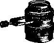
Abbe's experiments consist of the following. If a diaphragm is inserted into the drum that covers everything except the primary maximum located in the middle (see separate table for the article Optics, Figs. 3-10), then no image will be obtained, and we will see only an illuminated field of view corresponding to the arrangement of the lines of the Abbe plate. By inserting a diaphragm wide enough for the primary maximum and the first spectra from the sparse system of lines to pass through, we will clearly see under the microscope a system of sparse lines and a bright band in place of the dense system of lines. By placing a diaphragm with three slits located at the site of the primary maximum and the first spectra from the dense system of lines (the second spectra of the sparse system), we will clearly see the dense system of lines, and in place of the sparse system, a doubling of the lines with a halving of the interval between the lines. Figure 23. Intermediate insert of the Abbe diffraction apparatus with a holder.
If the primary maximum is excluded and the secondary maxima are allowed to pass, the field of view will appear dark, and the corresponding structure will appear on it in the form of bright lines. On the Abbe plate, the phenomenon is not so noticeable due to the dark background on which the bright lines are drawn; but if one takes any other specimen, e.g., a set of diatoms, as shown in the table, the phenomenon appears very effectively (see separate table for the article Optics, Figs. 11-13). For all the indicated experiments, it is necessary to have a well-selected Zeiss aa system, for which the positions of the slits in the objective diaphragm are calculated. With a diatom specimen, one can also perform a series of experiments to confirm Abbe's theory. If one examines such a specimen under normal conditions with a narrow central diaphragm, diffraction colors are clearly visible on some diatoms with a fine structure; upon introducing a diaphragm with central darkening under the illuminator, a brilliant dark-field effect is obtained with bright lines of the specimen's structure and a change in diffraction colors; upon introducing a diaphragm with a narrow slit while illuminating with a flat beam of light, as in Abbe's experiments with the plate, one can see the distortion of the diatom structure in accordance with the spectra that the objective diaphragm allows to pass. A very convenient object for such an experiment, perfectly suitable for the Zeiss aa system, is the diatom Triceratium favus. Its shell represents a rather coarse triangle, filled inside with rows of round holes arranged in a checkerboard pattern. If one sets up a slit diaphragm and takes a narrow diaphragm that allows only the primary maximum from the Abbe diffraction plate to pass, then of the three systems of diffraction spectra, only those located in the direction of the slit of the objective diaphragm will pass, and the rest will be covered. With such a setup of the experiment, instead of round holes, we will see bright bands running parallel to one of the sides of the triangle. By rotating the drum with the diaphragm, one can see that these bands change their position and run parallel to another side. With the middle position of the slit, instead of round windows, rectangles are obtained, lying in a checkerboard pattern, elongated perpendicular to one of the sides depending on the direction of the slit of the objective diaphragm. Another suitable object is the pattern of closing plates in the striated border of the intestine; here, too, depending on the position of the slit, the network of polygon boundaries turns into zigzag lines that change their direction upon rotation of the drum (see separate table for the article Optics, Figs. 11-13). The conclusion from the indicated experiments are the following propositions: 1) the illumination of the field of view depends on the passage of the undeflected rays of the light source into the microscope - the absolute or primary maximum; their exclusion gives a dark field of view; 2) the structure visible in the microscope depends on the passage of secondary maxima (spectra), and for the construction of the image, at least one primary spectrum is necessary; 3) the use of secondary maxima (spectra) that are more distant (not the first ones) for the construction of the image entails a corresponding doubling (or multiplication) of the structural elements in the image. By means of a relatively easy geometric analysis of the path of rays from the secondary maxima, it can be shown that in the plane conjugate to the focus of the objective, an exact reproduction of the structure that produced the used system of spectra is obtained due to the interference of light (Fig. 24). As was indicated above and as can be seen from the drawing, Secondary image.

Fig. 24. Construction of the image in a microscope according to Abbe's theory: L-primary (absolute) maximum; L'-spectrum; s-distance between spectra; E-distance between elements of the structure in the image; LQ-difference in the path of rays LP' and UP'. From the analysis of the drawing, it follows that PP'[E] is equal to LL'[s] multiplied by the magnification of the objective; LL'-depends on the light source ~objective.
depends on the interval between the elements of the object's structure, i.e., the points of the image correspond to the arrangement of the points of the object. The angular distance of the spectra from the primary maximum is greater, the smaller the interval between the elements of the specimen's structure. At the same time, since secondary spectra are obtained due to the interference of light waves coming from the edges of the structural elements of the specimen, and the visible effect (i.e., the appearance of these spectra) can only be obtained with a difference in the path of the rays somewhat greater than half the wavelength of light, it is obvious that structures with an interval smaller than half the wavelength of light cannot be visible, as they will not provide the material for constructing a secondary image according to Abbe; in order to capture spectra spread out at a large angle and obtain fine details of the structure in the image, it is necessary to have an objective with a wide angle, i.e., with a large aperture. This can be easily shown by placing annular diaphragms on the upper lens of the objective or by using an objective with an iris diaphragm inside.
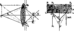
Figure 25.
Figure 26.
Figure 25. Entrance pupil of the lens S1S2; D-diaphragm; E1E2-its virtual image (entrance pupil) given by the lens; P1P2-points of the object; P'1 and P'2-points of the image; angle E1P1E2 and angle E1P2E2-aperture angle (the larger, the closer the object is to the lens); angle E1P3E2-aperture angle for a point not lying on the optical axis. Figure 26. Change in the aperture angle when moving into a medium with a higher refractive index: U-angle for air; V-for glass; u and u'-their halves (taken into account when determining the numerical aperture).
Such diaphragms, by closing the peripheral zone of the system, reduce its aperture. Having set up some specimen with a varied—coarser and finer—structure and reducing its aperture as indicated above, we will see the gradual disappearance of details, starting with the finest. In accordance with the theory of resolution of the microscope, the angle at which rays enter the objective of the microscope (Figs. 25 and 26) acquires special significance. In an optical system, there is usually a diaphragm placed between the members of the system, and in this case, the boundary of the light cone should be considered the rays drawn not to the ends of the lens diameter, but to the edges of the virtual image of the diaphragm given by the front lens of the system. This image is called the entrance pupil (Eintrittspupille) and plays a large role in the construction of the image by the system, since only those rays that do not go beyond the limits of the entrance pupil can pass through it. Correspondingly, the term exit pupil (Austrittspupille) is understood as the image of the system's diaphragm given by its subsequent members; it determines the bundle of rays emerging from the system and plays a less important role; however, in the microscope as a whole, it does not remain without influence on the image and, at very high magnifications, being very narrow, it causes diffraction phenomena in the eye, limiting the clarity of the image. The term aperture or angular aperture in optical systems refers to the angle formed by the extreme rays going from a luminous point to the ends of the diameter of the optical glass. Without touching upon mathematical calculations, it can be said that for an accurate characterization of the aperture and for the possibility of comparing different objectives, it is more convenient to express it as a numerical value, using trigonometric quantities, and one should take not the entire angle 'u', but its half 'a'. As a correction, taking into account the above-mentioned changes in the angle when passing into another medium, the refractive index 'n' of the medium located between the object and the objective should be added to this expression. In such a case, the aperture A = n sin a. Such an expression of the system's aperture allows for the precise calculation of the path of rays under all conditions and is an accurate characteristic of the objective's ability to resolve one structure or another.
From the analysis of the given formula, the advantage obtained in immersion objectives by placing a medium with a refractive index greater than air between the specimen and the objective becomes understandable. If for dry systems the aperture at best reaches 0.95 (limit 1.0), then in water immersion it is brought up to 1.25 (0.95 x 1.33 = n for water), and in oil immersion—up to 1.40 (0.95 x 1.51 = n for cedar oil). Oil immersion is called homogeneous, because the refractive index of cedar oil is almost equal to the refractive index of the front lens of the glass, and the rays from the specimen travel without noticeable deviation from their original direction. The higher the aperture, the more fully the diffraction spectra spread out at a large angle from the primary maximum can be captured by the objective, i.e., the finer the structures that can be reproduced by it.
It is quite understandable that diffraction spectra can only be obtained with distances between the elements of the optical grating of not less than 1/2 the wavelength of light (λ/2), and here, therefore, lies the limit of the resolving power of the microscope; what lies beyond this limit cannot be reproduced according to the Abbe theory, and if the structure is drawn, it cannot be reliable, and its elements cannot be accurately determined either in size or in shape.
Since for the construction of an image, according to Abbe, besides the absolute (primary) maximum, at least one secondary maximum (spectrum) is necessary, then according to the Fraunhofer formula, it is easy to calculate the distance between the elements of the grating that can be resolved by the microscope. According to this formula, the sine of the angle of deviation of the first spectrum (u' or a) is directly proportional to the wavelength (λ) and inversely proportional to the distance of the grating lines (e) and the refractive index of the medium n, i.e., sin u' = λ / e, whence e = λ / n sin u'.
Since the angle u' is equal to half the aperture angle (the spectra lie on both sides of the primary maximum at an angular distance u' = half of u) and we denoted it above by the letter a, the smallest reproducible distances of the structure elements can be obtained by dividing the wavelength by the aperture (n sin a).
In the case of full oblique illumination, when the primary maximum lies at the edge of the objective's field of view, one can catch a secondary maximum located at a double angular distance, i.e., in this case e = λ / 2n sin a (for a double aperture).
In direct connection with Abbe's positions is the question regarding the illumination of the specimen. According to Abbe's views, for the complete reproduction of the secondary image, one luminous point is quite sufficient, and therefore it is preferable to use a narrow beam of light. With a wide cone of light, individual points of the specimen are illuminated by different sections of the light source, i.e., by incoherent rays incapable of producing interference; therefore, individual images obtained from different points of the illuminating surface are simply superimposed on each other, as a result of which there is a blurring of the image contours. Indeed, unstained or weakly stained specimens do not give a sharp image with a widely opened condenser, and structural details disappear.
Criticism and corrections to Abbe's theory. Abbe's data could not fail to attract the attention of microscopists, both practitioners and theorists. The greatest interest is represented by the remarks and additions made by the well-known physicist Rayleigh. Accepting Abbe's theory in general, Rayleigh pointed out a number of cases that are inexplicable from the point of view of this theory and give a resolution of much finer structures than e = λ / 2A.
Figure 27. Image of points A-A, obtained in the plane Y; line c-distribution of intensity. Firstly, in Rayleigh's opinion, the Abbe condenser, by projecting the light source into the plane of the specimen, can make it self-luminous, and then the image should be obtained as a primary one. In this case, closely lying points of the object in the image will give diffraction circles, partially overlapping each other and summing the light intensity in these places; analyzing the distribution of illumination intensity, which makes it possible for the eye to distinguish the centers of the circles, Rayleigh arrives at the same value of the interval as Abbe and Helmholtz, i.e., e = λ / 2A.
2nsma (Fig. 27). If self-luminescence of the specimen points is not obtained, then two cases are possible here: the illuminating rays are incoherent and coherent. In the first case, no change in the resolution limit of the microscope will occur. In the second case, which is quite possible when illuminating with plane light waves, the diffraction circles, overlapping each other, will produce light interference, as a result of which the resolution limit is pushed far back (Figure 28). As can be seen from drawing III, with a path difference of half a wavelength, the circles will always be separated by a dark gap, and the resolution limit here is determined only by the drop in brightness of the centers of the circles as they approach each other. The same applies to the case of two lines. The situation is different if we have a self-luminous grating; with incoherent rays, it does not provide resolution even within the limits indicated by Abbe—at an interval of λ/2 it should produce a bright field. In the case of coherent rays, the limiting interval must fully correspond to the Abbe formula. If one examines a dark line on a bright background, then in the case of illumination by coherent rays arriving at the image plane with identical phases, such a line can be visible at a thickness of λ/39n, i.e., 16 times lower than the limit indicated by Abbe. If the background is self-luminous, then the limit is reduced by another 2 times, i.e., to λ/78n. But it turns out to be impossible to determine the width of the line, since it will always appear wider than the actual one. The development and criti
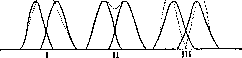
Figure 28. Case of coherent rays: I—rays in the same phase—merging of points; III—rays in opposite phases—dark gap, visible as long as this is accessible to the eye for physiological reasons; II—intermediate case, analogous to illumination by incoherent rays.
cal theory of Abbe continues to the present time. Rayleigh, as can be seen, somewhat pushes back the resolution limits of the microscope given by Abbe. Under certain illumination conditions, structures of a finer order can be visible under the microscope, but their exact shape still cannot be determined. Thus, in the current state of the science of the microscope, the theoretical limit of the resolving power of the microscope remains the Abbe and Helmholtz formulas with the indicated Rayleigh corrections. The real values of the indicated resolution limits of different objectives can be seen from the following table: Limiting Numerical Objective distance for direct aperture illumination B/λ for oblique illumination B/λ 0.3 Zeiss Apochromat 16 mm . 1.83 0.51 0.4 Zeiss System "C" . . . 1.37 0.68 0.5 Hartnack System 4 . . 1.1 0.55 0.65 Zeiss Apochromat 8 mm, Zeiss System "D" .... 0.84 0.42 0.95 Zeiss Apochromat 3 mm, Hartnack Systems 7 and 8 . . 0.57 0.28 1.25 Oil immersion 1/12 Hartnack . 0.44 0.22 1.3 1/12 Zeiss, apochromat 1.5 mm, 2 mm and 3 mm Zeiss . . . 0.42 0.21 1.4 Zeiss Apochromat 2 mm . . . 0.39 0.19 1.5 Semi-apochromat 1/16 Powell . 0.37 0.18 1.6 Zeiss monobromonaphthalene immersion .... 0.34 0.17 The figures are given for ordinary illumination with white light, assuming a wavelength of λ=0.55 μ, corresponding to the middle, brightest part of the spectrum. When using blue or violet light (λ=0.44 μ), the figures must be multiplied by 0.8. By using ultraviolet rays, it is possible to obtain a reduction of the limit to 0.1 μ on a photomicrograph. A further possibility to penetrate beyond the indicated limit of studying the structure of living matter is provided by research under conditions of ultramicroscopic observation (see Ultramicroscope) and the use of a polarizing microscope. Objectives are designated by letters of the Latin alphabet, numbers, or focal lengths in mm or fractions of an English inch. Initial letters and low numbers denote weak systems. This designation is now going out of use, and most factories are switching to characterizing objectives by designating the focus in mm with an indication of the aperture. In recent years, the Zeiss firm has been designating objectives by the number of their own magnification (5, 10, 20, etc.), also giving the aperture and focal length. Continental factories correct objectives for a tube length of 160 mm (Leitz for 170 mm), English ones are calculated for a tube up to 250 mm.
In terms of construction, objectives should be divided into two main types: achromatic and apochromatic; a middle place between them is occupied by semi-apochromats, or fluorite systems. Achromatic objectives have a smaller aperture, and therefore it is preferable to use apochromats for resolving the finest structures. The disadvantages of apochromats include their relative fragility: firstly, their hemispherical front lens, by its very shape, turns out to be weakly secured in the mount and can easily be displaced by various kinds of impacts (by pressure, by careless wiping and abundant wetting during cleaning, by changes in temperature, etc.); secondly, apochromats cloud over rather quickly, and they have to be sent back to the factory for cleaning and re-cementing of the optical glasses. However, recently, more stable apochromats have been released that are capable of withstanding significant temperature changes with impunity. The systems of optical glasses that make up the objective are firmly mounted in the casing and are connected at the upper end to an extension of the casing, which makes it possible to regulate the length of the entire objective so that when they are changed using a revolver, systems from the same firm almost exactly come into focus. Stronger systems (except for oil immersions) are equipped with a correction collar, which makes it possible to change the distance between the optical glasses inside the objective and thereby compensate for the change in the path of the rays that is caused by the cover glass (see below) (Fig. 29). A light ray that has passed through the cover glass enters the air or the liquid immersion medium between the objective and the cover glass. With a refractive index of the medium less than 1.515, the rays deviate from the norm at an angle that is greater the larger the angle of incidence of the ray. If we continue the series of rays that have passed through the cover glass from any point of the specimen backward until they intersect, they will no longer meet at one point, but will produce a line, which is longer the thicker the cover glass. Such aberration of rays is taken into account when designing objectives and can be corrected for a specific tube length by the corresponding arrangement of the lenses that make up the objective along the length of its casing. Usually, objectives are corrected for a glass thickness of 0.15 mm. For any other thickness of the cover glass, the system will turn out to be uncorrected, and to a greater extent the shorter the focus of the objective. Therefore, in some objectives—dry, medium, and strong, as well as in water immersion—a screw thread with a ring is made on the outer surface of the casing. By rotating the ring, we can move the front and rear halves closer together or further apart. Usually, the rear half is made movable, thanks to which the objective is prevented from going out of focus. Engraved on the ring are the figures for the thickness of the cover glass in hundredths of a mm. Some systems are arranged in such a way that the influence of the cover glass is not taken into account in them—these are objectives intended
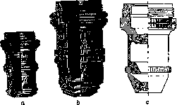
Figure 29. a—objective with various magnifications; b—objective in a correction collar; c—achromat 3.
specifically for the examination of objects in incident light without a cover glass. Their mount is made significantly shorter. On those objectives that have a correction mount, the relative position of the objective parts corresponding to a specific cover glass thickness is marked on the ring; knowing this value, it is possible to set the mount indicator directly according to the available glass thickness. If the glass thickness is unknown, then one has to set the correction mount by eye, which, with some skill, is achieved very easily. Usually, each objective is a certain construction with a specific focus, specific correction, and magnification; but there are objectives for low magnifications whose focal length can be arbitrarily changed by sliding the constituent optical glasses together or apart (for example, the Zeiss system a with an asterisk); there are also objectives that can be unscrewed and their individual parts used as independent objectives separately or in combination, e.g., the Winkel ABC system; for surveys of preparations with low magnifications, this provides great convenience, replacing a set of low-power systems. Besides objectives intended for ordinary microscope examination, optical factories manufacture special objectives for the purposes of projection, photomicrography, and polarimetric studies, as well as for the dark field of view. For projections and photomicrography, systems with a flat field of view are required; therefore, almost all firms manufacture special objectives for low magnifications, distinguished by an even and flat field of view, full astigmatism correction, and very good chromatic correction. These objectives provide a wide field of view, have high luminosity, and can be used both with an eyepiece and without one. These objectives bear various names: at Zeiss—Microtar, Microplanar, at Leitz—Microsummar, at Reichert—Micropolar, at Winkel—Microluminar. Objectives for examination in polarized light are arranged according to ordinary types, but they must have absolutely no polarization of their own; therefore, such crystalline bodies as fluorite are completely excluded from them, and the glasses used for their manufacture are especially carefully checked for optical homogeneity—there must be absolutely no lines and planes of tension that could result from the cooling of the glass. Objectives for the dark field of view are in some cases made with a blackened center to retard the absolute (primary) maximum, in other cases, like the Zeiss achromat 90, ap. 1.25, 2.0 mm or apochromat 60x with a pupil diaphragm to reduce the aperture and bring it into correspondence with the path of rays in paraboloid and Wechsel condensers. However, with the construction of the so-called Leuchtbildkondensor, there is no particular need for such a diaphragm, and one can use objectives with a normal aperture. Among the objectives for ordinary work in transmitted light, one should note the Zeiss achromat 6Ph and 40D*, which make it possible to examine objects in a small aquarium without a cover glass. Eyepiece. The purpose of the eyepiece is to ensure that the image provided by the objective (inverted, magnified, real) can be received on the retina in a magnified form and thereby facilitate the viewing of the details of the picture drawn by the objective. By construction, two main types of eyepiece are distinguished: the Huygens eyepiece and the Ramsden eyepiece. The Huygens eyepiece consists of two simple or achromatic glasses inserted into a cylindrical mount that easily enters the drawtube of the microscope; the eye lens is only the upper glass, while the lower one actually relates in its operation to the objective and is intended for converging the rays of the objective image into the plane of the diaphragm located inside the sleeve of the eyepiece mount. The presence of this lower glass of the Huygens eyepiece makes it possible to make the microscope tube shorter and to some extent improve the correction of the objective. The plano-convex glasses of the Huygens eyepiece are arranged so that their convex surface faces the objective and are located at a distance less than the sum of their focal lengths; the focal length of the lower lens is twice
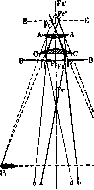
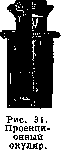
greater than that of the upper one, their common lower focal plane lies between the lenses, and the upper one above the upper lens. Therefore, the Huygens eyepiece cannot be used as a magnifier in the normal position; however, by turning it with the eye lens downward, it can be used as a magnifier with a short focus. In the Ramsden eyepiece (Fig. 30), the plano-convex lenses are turned with their convex sides toward each other; their focal lengths are approximately equal to each other and to the distance between the lenses. Therefore, both of its focal planes lie outside the eyepiece, and it can be used as a magnifier in the normal and inverted position. Thus, the real magnified image in the Huygens eyepiece is placed between its lenses in the plane of the eyepiece diaphragm and is viewed as in a magnifier with the help of the upper glass; the Ramsden eyepiece acts entirely as a magnifier, and in it, the image of the preparation provided by the objective lies under the eyepiece. The more common type is the Huygens eyepiece. Depending on the arrangement of the optical glasses of the eyepiece, it can be simple, achromatic, or compensation. Various firms manufacture differently correlated eyepieces for their semi-apochromats and apochromats, bearing the names orthoscopic, complanatic, etc.; essentially, all these eyepieces fit into the two main types mentioned above. Since in the Huygens eyepiece the image provided by the objective lies in the plane of the eyepiece diaphragm, which sharply cuts off the edges of the field of view, it is convenient to place various kinds of measuring instruments and devices for indicating a specific place in the microscope preparation here. For this purpose, the upper glass of the eyepiece is inserted into a separate sleeve, which easily slides in the main mount of the eyepiece and can be extended to set the diaphragm to focus, as well as for sharp setting of the divisions of the glass plate placed on the diaphragm and serving for measurements—a measuring eyepiece. For photomicrography, projection eyepieces are used, in which the eye (upper) lens of the eyepiece is inserted into a mount with a screw thread, allowing a large excursion of this lens forward and backward: this allows the focal length in the photomicrographic camera to be varied significantly while maintaining the sharpness of the outlines of the field of view of the image (Fig. 31). In some cases, the eyepiece is connected with additional apparatus. Figure 30. Path of rays in the Ramsden eyepiece: BB—eyepiece diaphragm; P1', P2'—image provided by the objective; P1 P2—final image provided by the eyepiece; Fc and Fc'—foci of the eyepiece; Fa and Fa'—foci of the eye lens A; Fe—focus of the collective lens C.
such as, for example, an analyzer eyepiece for examination in a polarized apparatus; here, a Nicol prism, serving as an analyzer, is connected to the corresponding eyepiece, which presents certain conveniences. Eyepieces are designated according to the magnification they provide independently, or by numbers, which seems less convenient and has been falling out of use in recent years. With this method of designating eyepieces, small numbers mean weak eyepieces, and higher ones mean a stronger intrinsic magnification. A reflecting prism can be attached to the eyepiece, making it possible to project the image obtained in the microscope onto the plane of the workbench onto a sheet of paper—drawing eyepieces. In some respects, they are very convenient; with their help, it is easy to sketch the outline contours of the preparation being studied for further, more detailed drawing of the preparation while studying it with an ordinary eyepiece.
Special types of eyepieces. 1) Pointer eyepiece. In a Huygens eyepiece, a thin metal hair, pointed at the end, is placed on a special extendable and rotating rod, the end of which lies in the plane of the diaphragm and can be moved in the field of view by the movement of the rod. It can be set at any point in the field of view of the microscope to point out an interesting place in the preparation to another person (Figure 32). 2) Double pointer eyepiece—a Huygens eyepiece having a side tube with an eye lens at the end, which can be moved in and out by means of a screw thread. In the plane of the diaphragm, there is the same pointer as in a simple eyepiece; above the pointer, a prism is placed, deflecting part of the rays into the side tube. Thus, the demonstrator looks into the microscope normally and sets the preparation and the pointer to focus for their eye, and another observer looks into the side tube, and, by adjusting the eye lens for their eye, simultaneously sees everything that is in the preparation and the pointer being set to interesting places. In the Zeiss pointer eyepiece, there is
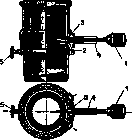
Figure 32. Reichert's pointer eyepiece in longitudinal and transverse (in the plane of the diaphragm) sections: 1—handle for the needle; 2—screw for fastening; 3—mounting for the needle; 4—screw for
knobs; 5—screw for fastening the eyepiece in the microscope tube. For demonstration, there are two tubes: one for the instructor, and the other for the student. The eyepiece is covered from above, the openings in the tubes are turned upward, and thanks to prisms with total internal reflection, both observers look in the usual, accustomed position. Above the diaphragm is placed a splitting
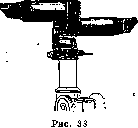
prism, giving equally clear images to both observers (Fig. 33). - 3) A comparison eyepiece consists of two sleeves with the lower lenses of a Huygens eyepiece, inserted into two microscopes. Both sleeves are connected by a horizontal tube, in which, at the ends, prisms are located above the lenses
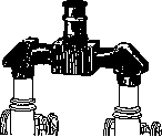
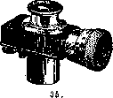
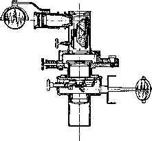
with total internal reflection. In the middle, two more prisms are placed, sending the reflection upward into the eye lens of the eyepiece. In this case, in one half of the field of view, the image from one microscope is visible, and in the other, from the other. Both reflections are separated by a thin dark strip. This makes it possible to compare two similar preparations from different objects and identical preparations under different treatments (Fig. 34). - 4) Eyepiece with a crosshair. In the plane of the eyepiece diaphragm, two thin threads are stretched perpendicular to each other along the diameters of the field of view, or a glass plate is placed with two lines drawn in the same way. The point of intersection of the lines serves to mark a location, as in a pointer eyepiece. - 5) Screw measuring eyepiece—a Huygens eyepiece, in which a plate of an ocular micrometer is placed at the level of the diaphragm, connected to a micrometer screw, on the head of which, placed on the side, one can count hundredths of a millimeter. Knowing the magnification of the objective, it is easy to make a very accurate measurement, more accurate than with the help of an ordinary measuring eyepiece (Fig. 35). - 6) Microspectral eyepiece. Above the Huygens eyepiece, a direct-vision prism is mounted on a hinge, giving a spectrum for the rays that have passed through the preparation; with the help of a system of a small mirror and a reflecting prism inside the eyepiece, it is possible to project into the field of view rays that have passed through a small tube with some colored solution; with the help of a second small mirror and a system of lenses, it is also possible to project a wavelength scale into the field of view. The apparatus can also be used without a microscope to study the spectrum of a liquid poured into a small tube, or the spectrum of vapors of a substance introduced into the flame of a burner (Fig. 36). - 7) Microphotographic eyepiece—see Microphotography. - To the eyepieces, one should also include the Zeiss "Homals," intended exclusively for projection and microphotography (see Homal). It goes without saying that with oil immersion or when examining objectives without a cover
glass, the correction mount is superfluous.
A condenser, or capacitor, is intended for concentrating light in the preparation and bringing the brightness of the image to a value at which the observer's eye can perceive the difference in the illumination of the elements of the preparation. From the foregoing, it is evident that the illumination of the image falls rapidly with an increase in the objective. In order to maintain sufficient image brightness, which is always less than the brightness of the object,
viewed by the naked eye, it is necessary that the bundle of rays emerging from the microscope fills the entire opening of the observer's pupil or is larger than it. In other words, the exit pupil of the microscope must be no smaller than the diameter of the eye's pupil. This exit pupil can be seen if one looks at the set-up microscope at a certain distance from above (for a normal eye, about 250 mm). Under this condition, we see a small bright circle, the so-called Ramsden circle, which can be received on a screen. Helmholtz calculated that normal image brightness is obtained at a perfectly definite magnification, namely 166.7 times; at a magnification twice as large, the image brightness falls by 4 times, at triple—by 9 times, etc. Thus, the brightness falls rapidly, limiting the "useful"
magnification. The condenser, on one hand, pushes back the limit at which, due to the drop in brightness, the eye loses the ability to distinguish nuances of illumination and color, and on the other, by providing a beam of light of one width or another corresponding to its aperture, it helps to utilize the aperture of the objective. It is clear that the aperture of the condenser must not be smaller than the aperture of the objective, because otherwise a part of it will remain unused. The aperture of the condenser is determined and expressed by the same values as in the objective, i.e., n sin a. Therefore, if we want to fully utilize the aperture of the objective, then between the condenser and the lower surface of the slide, a drop of cedar oil should be placed to turn the system (condenser-intermediate medium-slide) into a homogeneous one in terms of the refractive index. This is especially important with an oil immersion objective, very thin objects of study, oblique light, and examination in a dark field of view. Types of condensers. 1) A spectacle condenser consists of a chromatic lens in a cylindrical mount, which is inserted into the sleeve of the illuminating apparatus; it gives a very large field of view
Figure 36. Abbe microspectroscope.
and is used at low magnifications. 2) A complex condenser (Abbe) consists of two (aperture 1.2) or three (aperture 1.4) complex aplanatic or achromatic lenses. The first, most common, is cheaper (Fig. 37) and suitable for most work, but for delicate research with large apertures, a three-lens illuminator is, of course, necessary. - 3) A mirror plate condenser (Reichert) is placed on top of the stage and consists of a series of small lenses arranged in a circle: one ordinary, transparent for transmitted light, one covered with frosted glass, also for transmitted light, and the others with an opaque central diaphragm of different widths corresponding to different objective apertures and polished silvered edges, calculated so that the rays reflected from them give very obliquely directed beams intersecting at one point, located 1.2 mm from the surface of the illuminator (the usual thickness of a slide). This value is given on the illuminator. The preparation is placed on the illuminator as if on a slide
Figure 37.
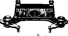
stage and is secured with spring clips. Between the illuminator and the preparation is a layer of cedar oil (Fig. 38). - 4) A variable condenser (Wechselkondensor Peterfi) makes it possible to quickly switch from a bright field of view to a dark one and vice versa. In the middle of it, with a handle protruding from the mount, an opaque central diaphragm is placed, which
Figure 39.

can be moved out of the center by moving the handle; in this case, conditions for image formation under normal conditions are obtained. With a central setting, light passes from the correspondingly polished side surfaces (silvered) and gives obliquely directed light rays and a dark field of view. It is not very suitable for research in transmitted light and is convenient only for setting up subsequent ultramicroscopic study or preparation (Fig. 39). 5) Paraboloid and cardioid condensers—well-calculated illuminators for a dark field of view, differing from each other in the corresponding curvature of the side reflecting surfaces, the arrangement of the glasses, and the aperture (1st—0.8, 2nd—1.05) (Fig. 40). All the indicated illuminators for a dark field (3, 4, and 5) cannot be used with objectives whose aperture is higher than unity (usually it ranges from 0.4 to 0.85), i.e., with dry systems or with a Zeiss objective with an internal pupil diaphragm (60x). - 6) The Leuchtbildkondensor built by the Zeiss firm makes it possible to use systems up to an aperture of 1.3 without placing a diaphragm on them,
which makes it possible to resolve
Figure 40. a—path of rays in a Zeiss paraboloid condenser;
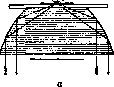
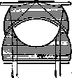
b—path of rays in a Zeiss cardioid condenser. on a dark field of view of very thin structures. The Leuchtbildkondensor (like the cardioid condenser) has a device for centering (Fig. 41). - 7) Ordinary objectives can also be used as a condenser for certain purposes. For this, special mounts are arranged with a device for centering, inserted into the sleeve of the illuminating apparatus (Fig. 42). - 8) Quartz condensers are arranged for the use of ultraviolet rays, which do not pass through ordinary illuminator glasses. Of course, the slide must also be made of quartz. If it is desired not only to act on the preparation with ultraviolet rays but also to conduct observation in ultraviolet rays, then all other glasses (cover slips, lenses, objec-
Figure 41.
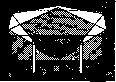
tives and eyepieces) must be made of the same material. - 9) A microspectral condenser makes it possible to project a spectrum into the plane of the preparation and study the effect of one or another monochromatic light on the object. An illuminator of a similar design, which gives a very wide spectrum, can be used for research in rays of a certain wavelength (Fig. 43).
Figure 42.
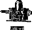
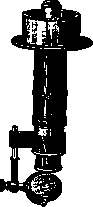
Figure 43.
Figure 43. Vertical illuminator (Vertikalilluminator, Opakilluminator). For the microscopic study of the surfaces of opaque specimens, illumination from above is required. The simplest device for this, used as early as the 16th, 17th, 18th, and 19th centuries by microscopists, is a collecting lens in a mount, either attached to the microscope or mounted on a special stand and concentrating light on the object under study. But short-focus objectives do not allow for this method of illumination, and since the end of the 19th century, reflecting prisms or mirrors have been introduced, installed in a transition drum between the objective and the lower edge of the microscope tube. These inserts have a window to which a system of lenses concentrating light onto the reflecting device can be attached. A beam of light, reflected by a small mirror or prism, goes through the objective from above onto the specimen, illuminates it with a concentrated beam, and enters the objective again. Due to the corresponding inclination of the surfaces of the prism or mirror glass, and in other cases partially passing by, the light passes through the entire microscope and provides a sufficiently bright image of the object (Figures 44 and 45). A vertical illuminator requires a bright light source (usually a small arc lamp or a strong incandescent bulb) and careful positioning of the light source, collecting lenses, and the height of the illuminator itself. Instruments for polarized light. For the study of optical anisotropy in microscopic specimens, two Nicol prisms are used, one of which serves as a polarizer and the other as an analyzer. In its simplest form, the analyzer, fastened in a sleeve with flanges, is inserted into a widely opened iris diaphragm or into a special ring under the condenser. The analyzer, also mounted in a sleeve, is placed on the eyepiece or on a special ring with graduations for reading the angle of rotation of the instrument, for which a fixed pointer is provided on the analyzer mount; for phenomena of colored (circular) polarization, gypsum and mica plates of a certain thickness and order are provided with the apparatus. The instrument is sufficient for rough polarimetric studies and is sufficiently inconvenient, since the polarizer in particular is fastened insecurely and in an indefinite position. For more precise studies, allowing one to detect not only the presence of anisotropy but also the nature of the polarization and the position of the axes, there are more precise instruments, as well as special stands (mineralogical). This includes the polarizing condenser: a Nicol prism as a polarizer is attached in the same mount to a three-lens condenser with an aperture = 1.0, which is inserted in place of the usual illuminator. To bring the illuminator into correspondence with the aperture of the objective, the upper and middle lenses can be unscrewed, the first for apertures 0.4-0.7, the second for apertures below 0.4. Gypsum and mica plates in a metal mount with markings are placed between the eyepiece and the analyzer. The remaining accessories—a quartz wedge, an Amici-Bertrand correction lens—are inserted into the corresponding sockets of the special microscope tube. Light sources. Normal is diffused sunlight (by no means direct), best reflected from a white wall or a cloud. With such illumination, which is quite sufficient on a clear sunny day, all colors retain their normal ratio and nuances. However, very often, and in some cases inevitably, one has to use an artificial light source. A very good light, approaching daylight, is provided by the incandescent Auer mantle of a gas-incandescent lamp, especially with the mantle facing down (Grecia lamp); a good light is provided by the Drummond burner. However, the most convenient and accessible is electric light. Any incandescent bulb
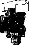
Figure 44.
with frosted glass is suitable for illuminating the microscope. Weak, so-called economic lamps give a yellowish light, and it must be corrected with blue cobalt glass, inserted under the illuminator or into the diaphragm ring on flanges specially arranged for this, or into a special ring under the diaphragm. Optical factories have released a whole series of models of lamps for microscopy, enclosed in special mounts that shield the burner from the eye and are equipped with collecting lenses and frosted glasses. As a collecting lens for ordinary electric and gas lam
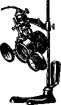
Figure 46.
ps, one can conveniently use a so-called cobbler's globe. It is a spherical vessel with a neck and a stopper, mounted on a stand with an opaque screen (usually wooden). A weak ammonia solution of copper sulfate is poured into the globe, which weakens the left part of the spectrum and gives the light a bluish, pleasant color for the eye. Special lamps for the microscope (electric). 1) Reichert microscope lamp; on a metal rod, fixed in a heavy cast-iron base on a clamping hinge, a half-watt electric lamp of 75 W is placed in a metal opening box, with a wire filament arranged in a vertical plane in parallel curves. The lamp has a folding collecting lens with a socket for frosted glass and a folding frosted glass in a mount (Figure 46). 2) Leitz lamp in the form of a cylinder with a collecting lens; mounted on a stand. 3) Carl Zeiss point lamp; in a spherical metal case, fixed on a heavy base and movable around a horizontal axis, an airless tungsten arc lamp is enclosed, forming a small, strongly glowing su
rface. A tube with a collecting lens, an iris diaphragm, and sockets for a frosted plate or light filters is attached to the globe (Figure 47). 4) Nernst lamp made of dwarf columns; gives a strong white light; convenient for photomicrography and projection, as well as for direct observation. 5) Reichert travel lamp; a low-voltage bulb of 4 volts and 1.5 amperes; can run from a dry battery, which makes it possible to use it even in the absence of an electrical network. It is connected to the ordinary network through a rheostat; it is attached to the rod of the lighting apparatus, but can also be attached to the stand. In some cases, the light source in the form of a low-voltage incandescent bulb, connected to the network through a rheostat, is mounted in the instrument itself, as is combined in the Reichert opaque illuminator (Figure 48), in the polarizing opaque illuminator, in the mirror condenser sliding into the sleeve of the lighting apparatus, or in the Zeiss skin microscope.

The Lilliput arc lamp is arranged in two modifications: with manual adjustment and with a clockwork mechanism that continuously brings the burnt ends of the carbons together.
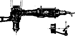
Figure 48.
Such a lamp is arranged for both direct and alternating current. The lamp consists of a metal box in which two thin carbons are inserted at a right angle to each other in special sockets connected to a regulating mechanism; the carbons can be brought together and moved apart by hand. Above the voltaic arc, a second box is installed on a hinge, of different shapes from different firms, covering the observer from the direct action of the arc light. On the side facing the microscope, a collecting lens and an iris diaphragm are inserted into this box, and there is also a place for inserting a light filter or cobalt glass. The lamp can be connected to any electrical network through a rheostat and draws about 4-5 amperes. When ordering, it is necessary to specify the type and voltage of the current. The light from the lamp is very bright and, besides direct observation, is suitable for photomicrography even with a short exposure, as well as for ultramicroscopic studies (Figure 49). Almost all lamps that give strong light (arc and large incandescent ones) emit many heat rays. To avoid overheating, especially when studying living objects, vessels with cooling liquid (water, a solution of alum or Mohr's salt, etc.) are placed in the path of the light beam. Such cuvettes of various shapes are necessarily equipped on the front and back sides with thin mirror glasses that do not change the direction of the light
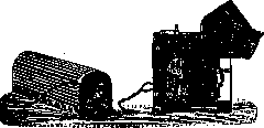
Figure 49.
rays, and are located on special stands (Figure 50). With subjective perception of the microscope image, as can be seen from the path of the rays in a complex microscope, the image is inverted (when projected onto a screen or the frosted glass of a camera, it is direct), which presents great inconveniences when dissecting with weak systems. For
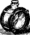
Figure 50.
To rectify the image, a Porro prism is inserted into the tube of the microscope, which provides an erect image during subjective observation. This device is especially necessary in the dissecting binocular microscope, where it is always installed (Figure 51). Supplementary apparatus for the microscope: 1) Objective micrometer; a microscope slide, usually in a metal frame, in the center of which divisions are marked in hundredths of a mm, and in some models, in addition, partly in tenths. The objective micrometer is placed instead of the specimen and is viewed through a measuring eyepiece (Fig. 52). Knowing the magnification of the microscope and the size of the micrometer divisions, it is easy to determine for a given objective and a given tube length the value of the divisions visible to the eye on the ocular micrometer (see Micrometry). - 2) A capillary rotator consists of a set of capillary tubes into which the specimen under study is placed. By rotating the head of the rod connected to the capillary, one can turn the specimen held by capillarity in the tube and study its entire surface. - 3) A prismatic rotator according to Greenough serves for studying small non-

Figure 51.
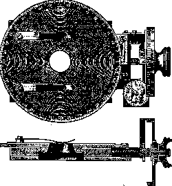
Figure 52. Stage micrometer with screw.
transparent objects, which are placed on a prism placed in a glass trough ground to the prism, and together with it can rotate and move. On the side, there is a second prism, allowing
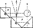
Figure 53. Path of rays in the Prismenrotator. P - prism; S1, S2, S3 - reflection of the surface; arrows show the path of the rays giving images in the plane of the microscope stage and the side planes.
one to see the side of the object; its upper side is visible directly, and the lower one - thanks to reflection in the prism. The path of the rays is visible in the draw-
ing (Fig. 53). - 4) Drawing apparatus. The camera lucida - the simplest drawing device - when applied to the microscope has the appearance indicated in the figure and is put onto the tube under the eyepiece (Fig. 54). In the Leitz or Zeiss drawing eyepiece, a prism is attached to the side, allowing one to see both the specimen and the tip of the pencil on the paper simultaneously. The large Abbe drawing apparatus is built on the same principle. It consists of a double prism in a frame, installed above the eyepiece and allowing the rays of the microscope to pass into the eye directly, and on the other side reflecting into the eye the image of the pencil and paper in a flat mirror placed on the side on a rod and capable of being set at different angles to the plane of the glass. The apparatus has two drums with smoked glasses of different density: one for the microscopic image, and the other for the mirror. By placing one or the other of the glasses, one can adjust the brightness of the two images so that a harmonious picture is obtained, which is easy to sketch. For setup, all parts under the eyepiece are easily moved to the side (Fig. 55). - The drawing and projection device of Reichert according to Vasiliu consists of a flat mirror, put onto the eyepiece and casting a real image onto the workbench. A small bulb in a special frame, put onto the illumination apparatus, serves for lighting. It is very simple and convenient to use
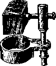
Figure 54
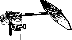
Figure 55. (Fig. 56). - 5) Marking apparatus; it resembles an objective mount and can be screwed into place. A diamond or a hard steel pin is embedded at its lower end, mounted eccentrically on a short rod or on the lower surface of the apparatus; by means of a screw, the distance of the point can be brought closer to the center (axis of the microscope) and moved away; this distance is easy to determine by the divisions of the head
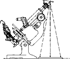
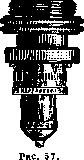
Figure 56.
of the screw (Reichert) or on the ring of the drum (Zeiss). Having set the necessary place in the center of the field of view, the apparatus is lowered onto the cover glass so that the spring under the diamond is compressed. By rotating the ring of the apparatus, a circle is scratched, by which it is easy to find the marked place again (Fig. 57). - 6) A thickness gauge for cover glasses is a drum with a dial indicating hundredths of a millimeter. The cover glass is inserted into side tweezers with a spring jaw, which is connected to the needle of the dial, indicating how many divisions the jaws of the tweezers do not converge, in other words, the thickness of the microscope slide (Figure 58). A heating stage in its simplest form consists of a copper plate Figure 58. Thickness gauge for measuring cover glasses. with two long extensions protruding forward, and a thermometer fixed on an inclined plate, also protruding forward. The plate, having a hole corresponding to that of the microscope stage, is placed on the stage of the microscope, and alcohol or gas burners are placed under its extensions. - A glass heating stage is a plane-parallel vessel into which
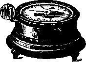
a thermometer and 2 tubes, inlet and outlet, are inserted on stoppers, through which water of a certain temperature is passed. - Leitz has released an electric heating stage with a thermostat, which is very convenient. Such a stage can also serve for cooling if a stream of liquid carbonic acid is passed through a special tube. All stages of such a design deserve criticism in that the specimen is heated from below, while the temperature of the surrounding air acts directly on the cover glass, which of course makes the setup of experiments with heating inaccurate depending on the different air temperature. - Zeiss provides a special cabinet on legs with a front wall made of mirror glass
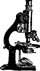
Figure 59.
; the bottom of the cabinet, covered with asbestos, is heated from below by a gas burner. The cabinet is equipped with a thermometer and a thermostat. The microscope is placed in the cabinet, which, with the exception of the head of the micrometric screw and the eyepiece, is at a certain temperature. On the side of the cabinet, at the level of the microscope stage, there are small doors through which one can set and move the specimen. This is the so-called heating microscope. Microscope, stands. According to the complexity of the design of the stand of the illumination apparatus, and in connection with this, according to the set of optics, stands are divided into small, medium, and large (universal). In addition, there is a number of special stands intended for specific purposes. - 1) A small stand in some cases does not have a rack and pinion, but only a micrometric screw. The illumination apparatus is often reduced to a plano-concave mirror or is limited to a single-lens (spectacle) condenser
. Figure 60. Diaphragms are cylindrical, sometimes iris, but without lateral movement and without rotation around the axis. Such are cheap school microscopes, equipped with weak systems for low magnifications, and "trichina" microscopes with a large stage, allowing one to place on it large thick glasses with pieces of meat being examined (Fig. 59 and 60). - 2) A medium stand always has a rack and pinion for coarse adjustment and a micrometric screw. Illumination apparatus with a two-lens condenser (ap. 1.2) and an iris diaphragm, in some cases rotating and shiftable to the side. Stand with inclination up to a right angle. The presence of such a mechanical arrangement makes it possible to use almost all optics with complete success, with the exception only of apochromats with high aperture (1.3-1.4). If fine laboratory research is not required, then this is the most suitable stand for practice, especially since the two-lens condenser can always be replaced by a three-lens one with an aperture of 1.4. The stage of such a microscope can optionally be quadrangular and round, rotating and movable. To replace a large cross-stage, all firms manufacture attachable movable cross-stages, for the fastening of which there are corresponding holes in the stand, allowing the apparatus to be precisely fitted to the stage (Fig. 61). - 3) A large stand can satisfy the most stringent requirements of laboratory research. It is equipped with a rack and pinion, a precise micrometric screw with divisions on the head, and a large illumination apparatus
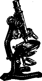
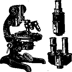
Figure 62.
with all movements of the pupil diaphragm and a large condenser. The tube is extendable, wide if desired (for photomicrography); one can have it with interchangeable tubes, single and double for binocular arrangement (Fig. 62). All improved supplementary apparatus and accessories, which can be purchased later, fit the large stand. - 4) The photomicrographic stand is equipped with a wide tube and a special movable
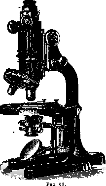
cross-stage. - 5) A mineralogical, or polarizing stand, built on the type of the large stand, has a special illuminator with a polarizer and a system of slots in the tube for placing a quartz wedge,
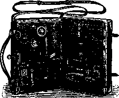
Figure 64.
mica and gypsum plates, an Amici-Bertrand lens, an analyzer with a correction lens, and a round rotating stage, the limb of which is divided into degrees with a vernier (Fig. 63). - 6) Travel microscope. The stand of such a microscope folds; its leg has the shape of an angle, and in the folded state - a narrow plate; the stage is either removed or turned 90° and takes a vertical position. In the folded state, the microscope is packed into a flat portable case, in which slots are made for objectives, eyepieces, cedar oil, and necessary instruments (Fig. 64). - 7) Skin microscope (capillary microscope), a small stand without a stage, applied directly
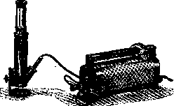
Figure 65.
with its round leg towards the object being studied. With its help, one can also examine pieces of tissue, metal plates, etc. A small light bulb in a special case on the stand serves for illumination, lighting the object from above (Fig. 65). - 8) Dissecting Microscope with weak objectives, giving a large field of view and usually an erect image thanks to Porro prisms (Fig. 66). - 9) Measuring Microscope (horizontal measuring Microscope) consists of a horizontal tube mounted on a high sliding stand. With a weak objective and eyepiece, it makes it possible to measure small
Figure 66.
Figure 67. changes of an object in vertical directions, to register oscillations of a string galvanometer on a photographic plate, to perform fine adjustment (e.g., in A. Gurwitsch's experiments on induction, etc.) (Fig. 67). - 10) Microscope for brain sections with a large table (20 x 20 cm) and a tube protruding forward. Convenient for examining large sections (Fig. 68). - 11) Sledge Microscope for viewing very large sections and cultures in dishes. The tube moves from left to right on a sledge; a specially designed stage moves from front to back with a rack and pinion. This makes it possible to view the entire object field by field. Magnifications are small; without an illuminator (Fig. 69). - 12) Plate Microscope - a small Microscope with weak objectives, the object stage of which is designed as a sufficiently large circle with sockets for preparations. The circle is fixed so that when it is rotated, the preparations come under the objective in a sequential series. Convenient for mass demonstrations and exhibitions. - 13) Binocular Microscope (often called a dissecting loupe), according to Greenough, with two objectives and two eyepieces, is currently manufactured by all firms. Two tubes, diverging at an angle of about 7.5°, contain Porro prisms; each tube has
Fig. 68. its own objective and eyepiece. The objectives are strictly calibrated for full identity, are located on a sledge at the indicated angle and are centered once and for all; each pair can be replaced by another of a different power. The eyepieces are mounted in drums, which, thanks to an eccentric hinge, can be moved together and apart, whereby the distance between the centers varies from 57 to 77 mm. The glass mirror stage has two plates - white and black - for episcopic study on a white and on a black background. A mirror serves for illumination. The tube moves up and down with a rack and pinion. It can be removed and transferred to a heavy stand for a loupe, allowing it to be used as a dermatoscope, and
Fig.
also for studying or dissecting objects that do not fit on the object stage. One can also have a second monocular tube. Zeiss provides seven pairs of objectives and 8 pairs of eyepieces, making it possible to vary the magnification from 8 to 336 times. One pair is designed as a water immersion and serves for studying objects in water. Inclined hand rests are attached to the stand. Stereoscopicity in this Microscope is complete. For the binocular Microscope, the Zeiss stand provides a stereoscopic camera according to Drüner with an attachment for enlarging images, which are very small in direct projection. Thus, one can make stereoscopic photographs, e.g., of embryos (Fig. 70). The binocular Microscope allows the use of only weak objectives not exceeding 12-fold magnifi-
Figure 70.
cation. For higher magnifications, the binocular Microscope is arranged according to a different principle: with one objective and a double tube (similar to old English ones). The original type is the Reichert stereo-attachment and the Zeiss bitube. Such an attachment is inserted instead of an eyepiece and appears quite bulky, especially the Reichert attachment. The path of the rays and the method of obtaining two images is clearly visible in the accompanying figures (Fig. 71 and 72). This attachment can also serve as a binocular loupe with a special stand (at Reichert's). Much more perfect and convenient is the so-called single-objective binocular Microscope. A large stand with all improvements, with an interchangeable tube, slides for a revolver or sledge apparatus, slides for changing condensers, etc. Carefully calibrated paired eyepieces, precise centering, good reflecting prisms that split the image, give the impression of stereoscopicity in the preparation, as from two objectives (Fig. 73). - 14) Luminescence Microscope; with the aim of making it possible to use short waves of ultraviolet rays, the Zeiss firm built a Microscope with all-quartz optics, giving an image on a surface with uranium salts, in
Figure 71.
which ultraviolet rays cause fluorescence. Thanks to this, the image given by ultraviolet rays becomes visible to our eye. A Leiden jar of a special design serves as the light source. Light from sparks is decomposed by prisms so that only ultraviolet rays enter the Microscope. - 15) Drawing Microscope (embryograph, according to Edinger) (Fig. 74 and 75); Microscope, illuminated by a Lilliput lamp from above, looks down with an eyepiece; thanks to this, an image of the preparation is obtained on white paper on the table, which can be drawn. The device makes it possible to use different objectives - from weak to the strongest immersion ones. Choice of Microscope. When choosing a microscope, one must be guided first of all by the purpose for which the apparatus is being purchased. If [Figure 72. Path of rays in the Reichert binocular attachment: A - attachment for the microscope; P - space for prisms separating rays for the eyepieces; K and K2 - eyepieces, G - rack head for moving eyepieces apart; O - collecting lens under the prisms; RM - toothed head for changing the position of attachment L; C - rim holding the attachment in the microscope tube.]
Figure 73.
one does not intend to perform fine microscopic research, then it is best to limit oneself to a medium or even a small stand. In any case, it is better to acquire a good stand with limited optics, which can then be supplemented, as well as additional apparatus. - Factories of Microscopes. Undoubtedly
Figure 74. Drawing microscope (in position for projection).
the first place among manufacturers of Microscopes belongs to the firm Zeiss (Jena). Both the optical and mechanical parts of the Microscope of this factory are the height of perfection achievable at the present moment. Very good instruments, cheaper, however, carefully executed, sometimes excellent in idea, are provided by C. Reichert (Wien) and Leitz (Wetzlar). Microscopes from Hartnack (Potsdam) are also good and very durable. Among French firms, one should note Nachet, among Italian ones - Koristka, among English ones - Watson, among American ones - Krauss.
Figure 75. Drawing microscope (in position for drawing).
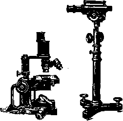

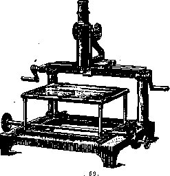
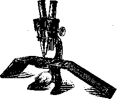
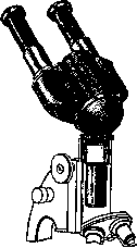
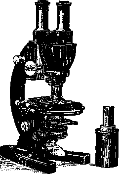
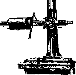
Related articles
Mentioned in
Cite this page
“Microscope.” Soviet Medical Encyclopedia. English translation of Bolshaya Meditsinskaya Entsiklopediya, 1st ed. (Moscow, 1928–1936), ed. N. A. Semashko. https://sovietmedicalencyclopedia.pages.dev/article/microscope/