Microphotography
Historical document, translated for reference. It reflects medical knowledge of the 1920s–30s and is not medical advice.
Summary
Microphotography is the process of obtaining photographic images of microscopic objects, typically observed subjectively through a microscope eyepiece. This method offers precision, objectivity, and speed in obtaining images, while also revealing details that may escape subjective observation.
Encyclopedia article (1928–1936)
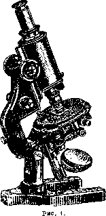
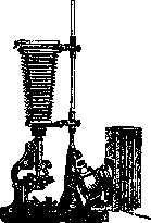
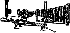
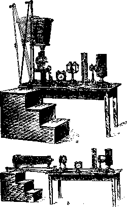
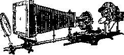
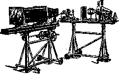
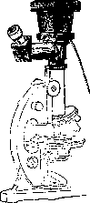
Microphotography, obtaining by means of photography images of microscopic objects, ordinarily observed subjectively through the eyepiece of a microscope. The main advantages—namely, the precision and objectivity of the images it provides, the comparative speed and ease of obtaining them, as well as the possibility of detecting details that escape subjective observation when using certain special methods—are the reason for the extremely widespread adoption of this method in all fields of knowledge where the microscope is generally applied. Microphotographic apparatus. In principle, a microphotographic apparatus is a photographic camera, the optical system of which is a microscope instead of a regular lens. Therefore, with the availability of microscopes, anyone can assemble a homemade microphotographic apparatus. The main part—the microscope—can be of any construction and quality, provided it is movably and light-tightly connected to the photographic camera. Many firms construct special "microphotographic" stands, equipping them with the best mechanical parts and highest quality optics. (Figure 1 shows the latest model of this type by C. Zeiss.) In such a microphotographic stand, its "wide tube" is striking; however, it should be said that this wide tube is absolutely necessary only for microphotography with the smallest magnifications (up to 30 times and less). Microphotographic apparatuses from various factories differ considerably. They can be divided into three groups: small (usually for plates of size 9x12; Figs. 2 and 3), medium (13x18 and 18x24; Figs. 4 and 5), and large (24x30; Fig. 6). For most work, 9x12 apparatuses are quite sufficient. They are usually adapted only for shooting with a vertically positioned microscope, which in no way detracts from the work. For more meticulous work, large-size cameras, capable of vertical and horizontal positioning and equipped with an "optical bench," deserve unquestionable preference. Large models are necessary only for the most delicate research. Of particular value in them (Fig. 6) is the independent positioning of the microscope with illumination apparatus and the camera itself on two separate stands. This method eliminates the transmission of vibrations from the illumination part to the camera, almost unavoidable in other apparatuses and extremely undesirable in precise work with high magnifications. To avoid the influence of vibrations, some large microphotographic apparatuses can be equipped with spring suspensions by special order. A large model with a long two-part bellows has very great extension, which is sometimes also very significant. The newest extremely diverse models of microphotographic apparatuses from various firms are currently equipped with a series of improvements that facilitate and speed up work. Large Zeiss apparatuses, despite their higher cost, better satisfy the basic requirements of geometric optics than others. In the following, such a model will be considered primarily as the most perfect. A special position is occupied by the special ocular-cameras, recently released by Zeiss, and later by Leitz and Reichert, which are attached directly to the microscope tube. All these extremely practical and convenient models also have the quite exceptional advantage of allowing observation of the object during the actual photography. Thanks to the presence of instantaneous shutters, such cameras can be used for instantaneous photography of moving objects with sufficiently intense illumination (Fig. 7). Basic prerequisites for M. Obtaining good-quality M., especially at high magnifications, largely depends on eliminating any vibrations during photography; therefore, it is advisable to use a separate room, preferably on the ground floor, for microphotographic work; during exposure, one must carefully avoid any jolts, people moving around the room, etc. It is very advisable to work in a dimly lit room and absolutely necessary to eliminate any excess light falling directly on the preparation and microscope. All lenses must be in a state of perfect cleanliness. The presence of dust causes light diffraction and harms the image. One should carefully avoid excessive cleaning and wiping of lenses. It is best, after carefully cleaning them with chamois or a soft old linen cloth, to avoid in the future any touching of the glasses with fingers. Dust should be brushed off with a soft wide brush. Almost every microphotography has its own specific characteristics, and therefore for the worker it is very important to be familiar with the theoretical foundations of image formation and to be able to understand individual cases.
Fig.
Vertical Zeiss camera.
Fig. 2.
Small size.
Fig. 3.
Small size.
Figure 4. Zeiss camera 18x24: a-in vertical, b-in horizontal position.
undoubtedly deserve preference for more meticulous work.
Figure 5. Universal Reichert apparatus 13x18.
positioning of the microscope with illumination apparatus and the camera itself on two separate stands. This method eliminates the transmission of vibrations from the illumination part to the camera, almost unavoidable in other apparatuses and extremely undesirable in precise work with high magnifications. To avoid the influence of vibrations, some large microphotographic apparatuses can be equipped with spring suspensions by special order. A large model with a long two-part bellows has very great extension, which is sometimes also very significant. The newest extremely diverse models of microphotographic apparatuses from various firms are currently equipped with a series of improvements that facilitate and speed up work. Large Zeiss apparatuses, despite their higher cost, better satisfy the basic requirements of geometric optics than others. In the following, such a model will be considered primarily as the most perfect. A special position is occupied by the special ocular-cameras, recently released by Zeiss, and later by Leitz and Reichert, which are attached directly to the microscope tube. All these extremely practical and convenient models also have the quite exceptional advantage of allowing observation of the object during the actual photography. Thanks to the presence of instantaneous shutters, such cameras can be used for instantaneous photography of moving objects with sufficiently intense illumination (Fig. 7). Basic prerequisites for M. Obtaining good-quality M., especially at high magnifications, largely depends on eliminating any vibrations during photography; therefore, it is advisable to use a separate room, preferably on the ground floor, for microphotographic work; during exposure, one must carefully avoid any jolts, people moving around the room, etc. It is very advisable to work in a dimly lit room and absolutely necessary to eliminate any excess light falling directly on the preparation and microscope. All lenses must be in a state of perfect cleanliness. The presence of dust causes light diffraction and harms the image. One should carefully avoid excessive cleaning and wiping of lenses. It is best, after carefully cleaning them with chamois or a soft old linen cloth, to avoid in the future any touching of the glasses with fingers. Dust should be brushed off with a soft wide brush. Almost every microphotography has its own specific characteristics, and therefore for the worker it is very important to be familiar with the theoretical foundations of image formation and to be able to understand individual cases.
Figure 6. Large Zeiss camera.
Illumination. When proceeding with microphotography, first attention is paid to the correct relative positioning of the microscope and camera: both parts must be installed strictly on the same optical axis and securely fastened. Next comes the question of illumination—the main factor on which all final results depend. The illumination of the specimen must be strong and uniform, and for this purpose, in addition to the Abbe illuminator (condenser) already present in the microscope, it is necessary to resort to the aid of various auxiliary lenses, as well as to take care of the proper selection of the light source itself. Scattered daylight or direct sunlight is hardly used for M. due to a number of difficulties. From sources of artificial light, theory from the point of view of M. requires the greatest possible intensity, with a sufficiently large luminous surface area with the greatest possible uniformity of its heating in all points. To one degree or another, any light source can be used, and if the first requirement is neglected, then a good kerosene lamp with a flat wick may prove to be quite suitable. However, it is clear that the convenience of electric lighting is so great that at present it is almost exclusively used. As is known, the voltaic arc (of direct current) stands first in terms of intensity (after direct sunlight), and this circumstance forces one to resort to it precisely in those cases of M. where this intensity has predominant importance. However, the use of the voltaic arc has a number of inconveniences, and in most cases efforts are made to replace it with other sources. For example, 'point lamps' (Punktlampen) are very perfect. However, they are short-lived, require very skillful and careful handling, and are expensive. Ordinary incandescent lamps, including half-watt ones, are little suitable due to the elongation of their glowing filament. They are successfully replaced by so-called projection incandescent lamps with a special filament arrangement, and even better—low-voltage lamps with a thick filament. Since such lamps are also quite expensive, it is strongly recommended to connect them through a suitable regulating rheostat, using their full brightness only at the moment of exposure. In this way, their service life can be increased 5-6 times. Whatever the light source, a special biconvex lens, the so-called collector, equipped with an iris diaphragm, is absolutely necessary for its use. This is due to two reasons: first, the luminous surface of all the sources described is still insufficient in area, and second, for its proper use, it would have to be placed in close proximity to the microscope's condenser, which is obviously impossible. By projecting with the collector an enlarged image of the luminous surface onto the plane of the Abbe illuminator's diaphragm, both these difficulties are eliminated. The collector is placed near the light source on the optical bench (a massive metal rod). On the optical bench on a special stand—a rider—the collector can be moved closer and farther from the light source and fixed in any position. In the same way, other additional lenses, as well as special vessels with plane-parallel glass walls (Fig. 6 and others), are installed. Placing the light source at some distance from the microscope is also important because this significantly weakens the harmful effect on the specimen and the microscope itself from excessive thermal rays. Often it is necessary to go even further and install on the optical bench 'heat filters,' i.e., the aforementioned vessels with plane-parallel glass walls, filling them with water or, better, a solution of Mohr's salt, potassium or iron-ammonium alum. The same cuvettes, filled with solutions of coloring substances, are also light filters (see below). A. Köhler (A. Köhler) established a very important position according to which the specimen will be illuminated most strongly and evenly if all optical systems are set up so that in the plane of the specimen the diaphragm of the collector is projected as well as possible. This position is in turn implemented on the condition that the light source will be projected as well as possible into the plane of the illuminator's diaphragm. Thus, a rule is formulated that helps to resolve one of the most important preparatory tasks—proper illumination of the specimen. According to this, the primary task of the worker is to 'center' the light source relative to the properly secured microscope. When working with a vertically standing microscope, the microscope's mirror is covered with a piece of paper, and with the help of available devices, the light source is moved up-down, right-left until it takes the correct position; by moving the collector, the light source is projected, at least approximately, onto the mirror. Further, by moving the mirror, the beam is directed onto the illuminator's diaphragm. It is advisable to temporarily place a piece of gray paper in the plane of the diaphragm and on it, by moving the collector, obtain the clearest possible image. Further minor adjustments are achieved by moving the mirror. For horizontal photography, the microscope's mirror is removed and aiming is done in the same way directly onto the diaphragm (or onto paper). It is very important that the image as possible fills the entire diaphragm without going beyond its limits. In his setups, Zeiss introduces on the bench a special lens Z70, which has a device for moving right, left, up, down, facilitating the final fine adjustment (Fig. 8). The light beam, directed onto the plane of the condenser's diaphragm, after being refracted by its lenses, subsequently enters the objective and eyepiece of the microscope. The Abbe condenser plays an extremely important role in image formation during subjective observation, which most practical microscopists usually underestimate; in projection, its importance becomes decisive. The Abbe illuminator is essentially an inverted microscope objective with a focal length of about 10-12 mm. As indicated above, its task in this case is to project as sharp an image as possible of the collector's diaphragm into the plane of the specimen. Unfortunately, ordinary microscope illuminators, not corrected
-il
Figure 7. Eyepiece-camera ITetica 'Fokua'. for spherical and chromatic aberration, are not able to fully solve this task. Therefore, for M. it is very desirable to use more perfect (and expensive) illuminators: an aplanatic one or even better—an achromatic one (Fig. 9). One can use weak microscope objectives as an illuminator, using a special mount for this purpose. With very precise construction of an achromatic illuminator or when working with an objective, particularly precise adjustment of these parts along the optical axis of the microscope is required, which is achieved with a special device. To obtain good M., it is very important to fully master the condens
Figure 9. a—aplanatic condenser ar. 1.4; b—achromatic condenser ar. 1.0; c—centering mount for using weak objectives as an illuminator.

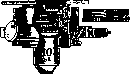
the microscope and learn to properly use the diaphragm of the apparatus. If we place any preparation on the microscope stage, having previously sufficiently narrowed the diaphragm of the condenser, we will not see the expected image of it on the preparation - for this it is necessary to move the entire illuminator (condenser) somewhat back. Having thus established the image, one should again correct the projection of the image of the light source onto the condenser diaphragm by moving the condenser or the centering lens. If now, opening the condenser diaphragm, we observe the strongly illuminated preparation, we will notice that narrowing the mentioned diaphragm begins to limit the illuminated part of the preparation, but has almost no effect on the brightness of the illumination. On this basis, the condenser diaphragm can be called the field diaphragm (Figure 8, Dt). Its use has its important significance for the quality of photograms, and here one can establish a firm and invariable rule: the field diaphragm should never be opened wider than the limits of the preparation directly subject to photographing. The excess light falling on the preparation is of no use whatever in photography; on the contrary, by creating unnecessary reflections, it greatly affects the clarity of the negative. Let us now turn to the study of the action of the condenser diaphragm. Let us equip the microscope with an objective and an eyepiece for subjective observation; in order not to harm the eyes from very strong light, it is necessary to reduce the incandescence of the lamp with a rheostat or otherwise weaken the illumination (for example, by placing a thin paper somewhere in the path of the beam). Narrowing the condenser diaphragm, we notice that it no longer has any effect on changing the size of the illuminated field, but on the contrary, moving it strongly affects the intensity of light and the character of the image: the intensity of illumination decreases, while the sharpness, clarity, and depth of the picture increase. If, greatly narrowing the diaphragm and removing the eyepiece, we look at the rear lens of the objective, we will see only a small bright circle in its center; if we begin to open the illuminator diaphragm, the bright circle will expand; in other words, we see that the diaphragm of a properly set condenser directly controls the effective aperture of the objective - its aperture; therefore this diaphragm is called the aperture diaphragm (Figure 8, D3). Gradual opening of the diaphragm expands the pupil of the objective to its full aperture, determined by the frame of the glasses. In most cases, the condenser diaphragm at this moment will be far from fully open. Naturally, further opening of it can no longer have any effect on the objective. The moment when the diaphragm aperture 'coincides' with the full aperture of the objective shows that now the apertures of the illuminator and objective are equal; with further increase, the condenser aperture becomes larger than the objective aperture; in the opposite case - smaller. The condenser aperture has decisive importance for the character and properties of the image; however, here it is extremely difficult to give any precise guiding instructions - the size of the diaphragm is determined by the peculiarities of the preparation and the desire of the photographer to give the microphotogram one or another character. From what has been stated above, however, it is clear that the use of a condenser aperture larger than that of the objective is quite impractical; on the other hand, theory and practice show that reducing the aperture beyond a certain limit causes diffraction phenomena and also harms the image. Some practitioners of M. recommend photographing at 2/3 of the objective aperture. It is still more correct to be guided by the properties of the preparation. Objectives. When working in M., one should undoubtedly give preference to apochromats. However, achromatic lenses when using light filters are also quite suitable. It should also be noted that in microphotography it is incomparably more advantageous for changing objectives to use not a revolver, but a saddle-like device that allows for more precise centering. In choosing the number of the objective, one is generally guided by the following basic rule: use stronger numbers for higher magnifications, and not resort to strong eyepieces or excessive stretching of the bellows. However, one should remember that increasing the power of the objective is associated with a decrease in its depth, which is extremely disadvantageous for microphotography. Therefore, sometimes it turns out to be very useful to photograph with smaller numbers and subsequently make enlargements from the negative. It is also sometimes very useful to use side illumination. Eyepieces. The eyepieces commonly used in microscopy, compensating and Huygens, are little suitable for M. 1) They are designed for subjective use and cannot, with normal adjustment, give a projection onto a ground glass. For this it is necessary either to slightly extend the upper lens of the eyepiece (the more so the closer the ground glass is located) or to move the entire microscope tube slightly with a micrometer screw; the first is troublesome and inconvenient, the second disrupts the correctness of lens calculations and harms the image. 2) The mentioned eyepieces give significant curvature of the field of view. In subjective observation, little attention is paid to this, since continuous work with the screw corrects the unevenness, but in M. this defect ruins the work, since we will constantly have on the photograph either a sharply centered center and unclear edges or vice versa. A long time ago Zeiss proposed special projection eyepieces, which fully resolve the first difficulty, but do not correct the convexity of the field. At present, both defects have been eliminated by recently issued Zeiss eyepieces for M., so-called homals. There are 3 numbers of them, all of the same magnification, but different for objectives of different focal lengths. Homals belong to the type of compensating eyepieces, i.e., they are suitable for apochromats (and strong achromats) and only in stands with wide tubes. They are quite unsuitable for subjective observation. It should however be noted that many firms at present produce eyepieces for subjective observation with significantly corrected field curvature. Such 'plan-eyepieces' of Reichert, periplanatic Leitz eyepieces, etc., are naturally more convenient also for microphotography. Light filters. The absolute necessity of using light filters in M. is based on the following. 1) The photographic plate 'sees' objects not as our eye does. Figure 10 shows a diagram of the spectrum of all greatest
greatest brightness for
""
brightness of the eye
600 550
400 red orange yellow green blue violet Figure 10: rays perceived by the eye, with the most effective part of the spectrum for the retina of our eye, i.e., the most "bright" being the yellow part with wavelengths from 530 to 620 mμ. On a separate plate (for the article Neurofibromatosis, Figure 2) is a photograph of the spectrum on an ordinary plate; here the greatest brightness lies between 425-480 mμ. Consequently, the plate renders light-yellow tones as dark, and dark-blue as light. 2) Ordinary non-apochromatic objectives, when rendering an image of a colorless specimen, essentially produce several closely positioned but not merging in one plane colored images of it. Making precise focusing by eye on the specimen and being guided by the yellow rays better perceived by us, we still do not achieve precise focusing for the plate, which more strongly perceives blue and violet images. 3) In M. one usually has to deal with microscopic specimens specially stained in various colors to highlight different parts; in this case it can easily happen that the plate will be unable to detect contrasts that are sharp to the eye. When using light filters, orthochromatic plates must be used, i.e., plates that also "see" yellow colors brightly, just like the eye. [Figure 1 (see separate plate for the article Neurofibromatosis) shows the spectrum taken on such a plate.] Sometimes panchromatic plates are used, i.e., plates sensitive to almost all colors. Light filters are various transparent colored media that pass through certain colors of the spectrum and absorb others. Liquid light filters are used, most often aqueous solutions of various dyes poured into the aforementioned cuvettes (Figures 6 and 8), and solid deeply colored glasses, glasses with a layer of colored gelatin or collodion applied to their surface, gelatin or collodion films. In all cases, such light filters are placed somewhere along the path of the light beam falling on the specimen. Perfect light filters for all cases are manufactured by the Lifa filter factory in Augsburg (Bavaria). If dyes are available, light filters, especially liquid ones, can easily be made independently; solid ones are more difficult to prepare. By including the necessary light filters in the lighting system, the above difficulties are eliminated, and achromatic objectives, which are absolutely essential for them, are equated to apochromats; however, even with the latter, light filters are still unavoidable in many cases. The main task of light filters is most often to weaken the excessive action of blue and violet rays, sometimes completely excluding certain colors. When working with stained specimens, many details of the specimen can be sharply highlighted by skillful selection of light filters (see separate plate for the article Neurofibromatosis, Figures 3 and 4). Each light filter is characterized by complete absorption of certain colors of the spectrum or at least their partial weakening. It is clear that from the total amount of light energy carried by the complex white light beam, a certain part, sometimes very significant, is held back in the light filter. For this reason, the use of light filters during photography inevitably involves lengthening the exposure time, sometimes two to three times, and sometimes hundreds of times. For any light filter, its absorption spectrum can be determined by special measurements, which gives a completely clear characterization of the given light filter. The choice of light filter for each individual case depends on the experience and knowledge of the worker (Figure 11). For making homemade light filters, a number of special organic dyes are needed; in many cases, however, one can do without them, using the Tsetnovsky green light filter. Staining Eosin Bismarckbrown Congo red Picricarmin Fuchsin, methyl violet Hematoxylin Heidenhain Methyl green...red Methyl blue...dark red Staining of light filters
"blue-green", "dark green" and "dark blue" are used only on panchromatic plates
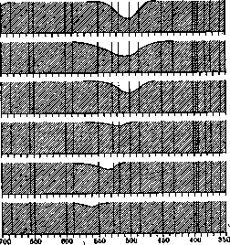
Figure 11. Absorption spectra of a number of Lifa light filters for the most common stains of microscopic specimens. The hatched part of the spectrum is absorbed by the light filter; the remaining light part is the rays acting on the plate. Letters at the top - designations of Fraunhofer lines; numbers at the bottom - length of light waves (in mμ). *1v (115 g copper sulfate, 11.5 g potassium bichromate per 1,000 parts water). It must be remembered that focusing must necessarily be performed with the light filter already in place. M. at various magnifications. The arrangement of instruments described above is intended for work with a strong objective, with an aperture of 0.6 and above. Under these conditions, after placing the specimen, it is necessary to take care only of the most precise focusing of the image on the ground glass of the camera. Careful correction of objectives with corresponding mounts for the thickness of the cover glass is even more important in M. than in microscopic observations. Here one usually resorts to the help of the so-called focusing loupe (Figure 12). In the most delicate work, instead of ground glass, transparent glass is installed, on which the image can be captured only by the aforementioned loupe. When working with weaker objectives, the described lighting and condenser arrangement is unsuitable. The illumination of the specimen in this case is bright but covers only a very small area of it in the center of the field of view. The usual practice in such cases of moving the condenser closer or farther in M. by no means can be allowed, as this fundamentally violates the entire principle indicated above. The correct measure is to remove the upper lens of the condenser, resulting in an illuminator with a smaller aperture and longer focal length (36 mm), which illuminates a larger surface of the specimen. At the same time, in Zeiss instruments additional lenses are introduced: an auxiliary lens HQQ is inserted into the collector, and Z40 is placed instead of ^70 (the number indicates the focal length), and the setup is checked according to the principle described earlier (Figure 13). With even smaller magnifications (up to 30 and less), the changes in the setup are even more significant. Photographs are taken not with ordinary objectives with microscope eyepieces, but with special systems used without eyepieces, so-called
Figure 12.


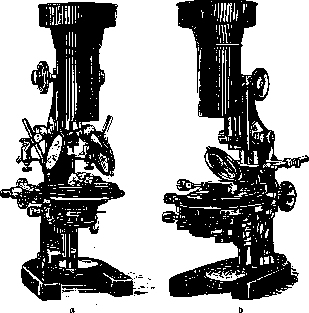
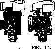
gg»,nbb F Z40 Figure 13. D3M planars and microtars of Zeiss, Leitz condensers, Reichert micropolars, etc., of various numbers, with focal distances from 35 to 100 mm. Due to their large focal distances and wide field of view, these objectives can only be fully used with stands having a wide tube, where the upper and lower flanges are removed and the objectives are attached to a special 'funnel' screwed in place of the eyepiece flange of the tube (fig. 4). The illumination system also changes fundamentally: the focal distance of the condenser, even when unscrewed, proves insufficient again and is removed entirely; in its place are introduced special lenses, the so-called 'eyeglasses' (Brillenglaser) of various focal distances, depending on the focus of the objective used. In the collector an auxiliary lens H100 is inserted and a new lens 'collective' K20, as well as the iris diaphragm D2, are introduced, which now serves as the aperture diaphragm (figure 14). Finally, when replacing the collector with two special large lenses and with the presence of a special stand, as well as a regular, good objective, this Zeiss setup can also be used for photographs in natural size or with 2-3 times magnification (brain sections, lantern slides, etc.). Guided by the above schemes for various magnifications on the most complete Zeiss setup with various additional lenses, the worker will be able without much difficulty to create possible optimal conditions for photography with more limited equipment or on other setups and even on a homemade apparatus with the most primitive means available. It is easy to see that success in M. depends much more on the correct use of available possibilities—understanding the set goal, knowledge of the photographic process—than on the equipment itself. M. in dark field. The difficulties in obtaining M. in dark field are almost exclusively due to the correct, strictly central setup of illumination. Photography can be performed with any dark field condenser. The most effective, but at the same time requiring F Z40 D2 Figure 14. Z20 D3M particularly careful adjustment, is however the cardioid-condenser of the latest Zeiss model. In all cases, the use of a voltaic arc is required; with sufficient skill and slight camera extension, instantaneous exposures are also possible. M. of opaque objects with incident light. The main difficulty when using even small magnifications consists in illuminating the object with light as steeply incident from above as possible (to avoid sharp shadows which could completely distort the appearance of the object). Zeiss attempts to solve this problem in two ways. a) On special holders above the specimen is placed a thin round ground glass, illuminated from the side by a very strong beam of light, and on the other side a concave or flat mirror is installed; as a result the object receives almost even shadowless illumination; neither glass should cover the objective (microplanar or other) (fig. 15a). b) On the path between the objective and the object is set at a 45° angle a very thin flat-parallel polished glass, not impeding the passage of rays from the object to the objective. From the side a strong beam of light is directed onto this glass, which (though with losses up to 50%) illuminates the object from above. With this arrangement it is possible to work at small magnifications with all special objectives of the planar type and others (figure 15 b). When using proper microscope objectives, even small ones, there is not enough space to position these illuminators properly. There are however special devices that allow the use of even strong objectives. Among these is e.g. the vertical illuminator of Nachet (fig. 16), which inside has a special prism reflecting onto the specimen light directed from the side. The prism covers half the effective aperture of the objective, i.e. reduces its aperture. Therefore this illuminator is not suitable for strong systems; besides it requires special shortened objectives and gives satisfactory results only when observing without a cover glass. Figure 17 shows the vertical illuminator according to Beck, where light is reflected from a flat-parallel glass. This model can also be used with strong objectives and in the presence of cover glasses. Despite the fact that both systems optically have a number of significant shortcomings, sometimes they prove very useful, espec
FIG. 16
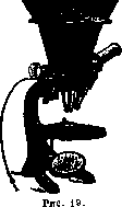
ially in metallurgy for photographing microstructures of alloys and the like. M. in polarized light requires knowledge of both the theory and practice of the polarizing microscope. The greatest difficulties are presented by photography at low magnifications (planars and others). For its setups Zeiss constructs special polarizers and analyzers, allowing to completely solve the corresponding tasks. Stereoscopic M. With the ever-increasing spread of binocular-stereoscopic microscopy, the importance of stereoscopic M. also grows. Indeed binocular microscopy and even more so stereoscopic M. often provides the key to understanding the most complex and difficult images, especially in cytological research (chromosome counting and the like). As is known, in a whole series of microscopic works, the 'binocular microscope' with two objectives and eyepieces, giving medium __________I magnifications up to 200-400 times, finds successful application. In this connection one should mention the stereocamera, long ago proposed by Dünner (fig. 18). The drawback of this stereocamera in its original construction was that microphotography was performed with the objectives alone without the objective magnification was very slight (30-40 times) with very shallow depth of focus due to the lack of illuminator and diaphragm in the objectives. To eliminate the latter drawback, the use of homemade diaphragms on the objectives can be recommended; the first drawback in the absence of a bellows on the camera remains unremedied. Only recently Zeiss has constructed a special attachment of two eyepiece systems of the homal type, quadrupling the objective magnification (figure 19). There is however another method for obtaining stereomicrophotographs with the help of an ordinary monocular microscope within all available magnifications. To obtain a three-dimensional image it is necessary, as is known, to have two photographs of the object made at some angle from two different viewpoints, in full accordance with how we see an object with the right and left eye. The required result can be achieved without much difficulty by two subsequent photographs: 1) with parallel movement of the camera (or only its objective) a certain distance relative to a stationary object or 2) with
movement of the object (with a movable stage) with a stationary camera. These techniques ensure full stereoscopic effect when photographing opaque objects with reflected light. With transmitted light, as is almost always the case in microscopy, such movement may prove insufficient. As indicated above, the primary importance here is acquired by the condenser illumination; by shifting the illumination axis, one can fully achieve the necessary differences between the right and left photographs. On this basis in his latest microscope models Zeiss equips the Abbe illuminator with greater movement to the right and left, which is marked on a special millimeter scale. For old models he offers a special 'stereoblend for condenser' allowing to achieve the same effect (fig. 20). |M. in rays of short wavelengths. The theory of image formation establishes that the resolving power of the microscope, i.e. the ability to distinguish the smallest details, is determined by two factors: 1) the size of the objective's aperture and 2) the length of the light wave in which the observation is conducted; thus an objective of a certain aperture makes it possible to distinguish more details of the object, the shorter the light wave. The size of the effective aperture of an objective made of glass under the best conditions practically cannot exceed the value 1.4. In the hands of the experimenter there consequently remains only one possibility for increasing the resolving power of the microscope—to work in the shortest possible light waves. Since short waves correspond to darker colors of the spectrum and the photographic plate 'sees' them more brightly and even perceives the invisible ultraviolet part of the spectrum, the importance of M. becomes particularly significant here. In practice subjective
Figure 20.

observation cannot be carried out below the limits of the bluish-blue color of the spectrum, i.e., below 550 mμ. The use of the bluish glasses usually attached to microscopes is a fiction from the point of view of increasing resolving power, since they pass a whole conglomerate of different rays. On the contrary, in M. of colorless transparent objects with large structural details, one can indeed 'see' significantly more, but on the condition of using M. in monochromatic light, i.e., in a beam of rays as homogeneous as possible in length. This can be achieved: 1) by including appropriate light filters that pass only a narrow segment of blue color (but such filters will inevitably be very dark, completely unsuitable for subjective observation); 2) with the help of a special 'mercury lamp' for microscopy (Zeiss construction), which gives a discontinuous, linear spectrum; by attaching to such a lamp even a relatively weak transparent light
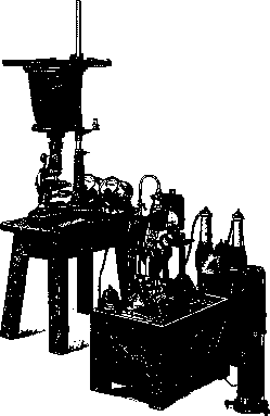
Figure 21.
filter, one can obtain an almost homogeneous beam; 3) by decomposing a complex beam with a spectroscope. When using instruments based on this principle, 'monochromators,' especially in combination with a linear light source, the best results are obtained. One can, however, go much further and take photographs already in the invisible rays of the ultraviolet part of the spectrum. According to the design of A. Köhler of Zeiss, a special type of microphotographic apparatus for ultraviolet rays was constructed (Fig. 21). The system consists: 1) of complex instruments for obtaining short-wave light rays (the light source is the flow of high-voltage electric sparks between cadmium or magnesium electrodes); 2) an optical bench on which are located a collector, a prism that decomposes the beam, and a prism that directs part of the spectrum into the condenser of the microscope; 3) the microscope and 4) the camera. All lenses, prisms, condensers, objectives, and eyepieces are made of quartz, not of glass, which is opaque to ultraviolet rays. Object slides and cover slips are also only quartz. Objectives, due to the necessity of constructing them from only a homogeneous material (quartz), are 'monochromats,' i.e., corrected for rays of only a specific wavelength. The object cannot be enclosed in Canadian balsam, so for this purpose water, paraffin oil, glycerin, etc., are used. Focusing is extremely difficult, as the invisible image is located by special 'finders.' Photographs of the structurally finest object—the shell of 'Pleurosiyma' algae—show the remarkable resolving power of the system. The wavelength at which the photographing is done here is 280 mμ. Color Microphotography. When it is necessary to obtain microphotography in the true colors of the object, one can use both autochrome and three-color methods (see Photography). The main condition for success here is the selection of filters corresponding to the light sources used, so that the difficult three-color method in itself becomes even more difficult in the context of microphotography; while the incomparably easier autochrome method is limited at high magnifications by the relatively large size of the colored starch grains in the emulsion layer of the corresponding plates. The quality of the negative material plays a very important role in microphotography. The first and most important requirement for the sensitive layer is its complete purity, as certain defects here can not only be unpleasant but also serve as a source of errors. From all that has been said above about the effect of various parts of the spectrum on the emulsion, it further follows that it is desirable, and sometimes necessary, to use ortho- or even panchromatic plates when working with multicolored objects. It is also extremely useful for the plates to be anti-halation. Halos, which are extremely harmful to image clarity, are particularly noticeable when there are large differences in illumination intensity in the object, which is often the case in microphotography. The danger of halation appearing drops almost to zero with films and special anti-halation plates, provided with a layer that absorbs actinic light between the emulsion and the glass (for example, Agfa Chromoisolar and Chromoisorapid plates), or on the back surface of the glass. If necessary and with skill, one can prepare plates of the latter category oneself, by applying to their back surface, for example, a solution of 50.0 aurine in 900.0 2% collodion with 100.0 warm strong alcohol and 4 cm3 castor oil or corresponding commercial preparations. The sublayers of the first category are bleached during 'normal plate processing'; if the same does not happen with those applied to the back surface, they either separate in water before development or have to be removed before printing. Plates of high sensitivity must be used in microphotography only for photographing rapidly moving objects, especially in dark-field illumination. In all other cases of using such plates in microphotography, they should be avoided. Most often in microphotography, work is done with emulsions of ordinary, medium sensitivity (70-90 on the Winn scale, 10-12 on the Scheiner scale). When it is possible to make longer exposures, working with low-sensitivity plates of the reproduction type can be extremely advantageous for obtaining the finest details and shades, as well as for obtaining particularly rich negatives. The same advantages are possessed by wet collodion plates at low cost, however, their use is extremely limited by the inconvenience that their emulsion retains sensitivity only for 2-3 minutes until it dries. These plates therefore have to be prepared immediately before use, and their preparation itself requires considerable skill and time. Finally, the emulsion should be as free as possible from 'chemical' fog, which is extremely unpleasant and harmful in microphotography in general. A test for the presence of fog can be made by immersing a part of an unexposed dry plate in the developer and keeping it there in complete darkness for as long as is usually required for this developer to produce a normal negative. In the complete absence of fog, after fixing there will be no difference between the developed and undeveloped parts; any darkening of the developed part will indicate the strength of the existing fog. On determining exposure. Determining the required duration of light action on the sensitive emulsion under given conditions to obtain a good microphotograph, i.e., determining exposure, is obviously also one of the most important conditions for success. This duration, as in ordinary photography, must be such that the darkening of various parts of the plate after development is proportional to the amounts of light received by them from the corresponding parts of the object. Beyond these limits of 'correct exposure,' the darkening of the plate parts will no longer correspond to the amounts of light reaching them, and the microphotograph will therefore not convey the density and color gradations inherent in the object. Most of the most important photochemical laws relating to this can be understood from consideration of the so-called characteristic curves of plate darkening. To construct such a curve, we will plot along the abscissa axis the logarithms of exposures E, equal to Jt, i.e., the products of light intensity by illumination time. Along the ordinate axis, we will plot the densities of darkening D, equal to the logarithm of the ratio of the intensity of light falling on the plate to the intensity of light transmitted by it, since here, as in other photochemical reactions, only the absorbed energy acts. By exposing parts of the plate at different values of E, we will see on the curve constructed in this way (Fig. 22) that with very small exposures, no darkening occurs at all (the corresponding values of E lie below the reaction threshold). Then the curve (middle, B), rising very gently, gives a concave section, which passes into a fairly long straight segment; further, the curve also gently bends in the opposite direction and begins to descend downward. A 'normal' exposure will correspond to the straight segment, in which obviously the darkening of the plate will be proportional to the products Jt; the initial concave segment corresponds to 'underexposure,' the upper sloping segment to 'overexposure,' and finally the descending part to the beginning of solarization, which can lead to obtaining a positive image instead of a negative. It should be borne in mind that numerically equal products J cause the same darkening only with small fluctuations in intensity and duration of light action; with larger shifts, the character of the curve can change significantly. In this case, a decrease in illumination intensity may require increasing the duration of light action in unexpected limits for us. The relationships conveyed by the curve will be reflected in the properties of the resulting negatives as follows. Below the reaction threshold (the distance of it from the ordinate axis characterizes the 'sensitivity' of the plate) we will not get any traces of the image; with extreme underexposures only faint traces of the most intensely illuminated parts of the object will be obtained, as here only they, and then only insignificantly, have passed the reaction threshold. Under normal conditions, these are completely useless photographs, completely dark, with barely indicated highlights of the brightest points. With lesser degrees of underexposure, the intensity of negative darkening in these most brightly illuminated points increases significantly and can reach great strength; meanwhile, only very limited categories of less brightly illuminated areas have time to cross the reaction threshold. As a result, we have extremely contrasty negatives (sharply black lights and transparent shadows) and prints with sharply white lights and extremely unsatisfactory detail rendering in all less brightly illuminated areas, which still print extremely dark. Next follows the straight part of the curve, corresponding to 'normal' exposure. The properties of the negatives and prints obtained here have already been described above.
This section has a certain duration and the angle at which the curve rises here may be different for different plates. Curve B, where angle a = 45°, refers to normal plates, whereas for rigid, contrast plates this angle is greater (curve A), and for soft plates it is significantly smaller (curve C). At the very beginning of the bend in the curve after the straight section, i.e., at the very beginning of overexposure, we get very dark, rich negatives in which details in the highlights begin to disappear, but the shadows are still sufficiently transparent. In the prints we also get contrasty pictures from them, but unlike the underexposure contrasts, the negatives here are generally dark, the prints are generally light, and the contrast is created only due to the disappearance, smoothing of details in the highlights. Moving up the sloping curve leads to greater and extreme degrees of overexposure, characterized already by a decrease in contrast: in fact, in the negatives the intensity of blackening in the highlights no longer only does not increase, but may even decrease (beginning of solarization); at the same time, less intensely illuminated areas manage to send to the corresponding areas of the plate such significant amounts of light that in them almost equally intense blackening is achieved. As a result, we get uniformly gray or black negatives that give pale, monochrome copies, devoid of any richness and details. Finally at the top of the curve we will have uniform blackening of the entire plate. Taking into account all the above about the significance of one or another shortcomings of negatives, one, by changing the exposure in the opposite direction, can select the required duration purely by experimental method on trial shots. With considerable skill this is usually achieved quite quickly, but even such experience cannot always save from the need to spend several plates. It is therefore better to give several different exposures on one plate at once, gradually pulling out the cassette cover each time by 1-2 cm and repeating the same exposure at the same time. Zeiss supplies its large installations with special cassettes making this operation more convenient. Special exposure meters represent exceptional conveniences for quick and accurate determination of exposure, supplied by Zeiss and Reichert with small cameras with side viewfinders (see above). The glass scale placed in front of the plate is divided into 7 sections. The extreme one, marked with the number 100, is completely transparent glass; the neighboring one, marked with the number 50, lets through only half the light. The following sections, marked with numbers 20, 10, 5, 2 and 1, are darkened successively so much that they let through only 1/5, 1/10, 1/20, 1/50, 1/100 of the light obtained with an uncovered plate under the given conditions. Let, placing the exposure meter in front of the plate, we gave for a trial an exposure of 10 sec. and, after developing, obtained the best result on the strip marked 5. We therefore need to reduce our trial exposure 20 times or take 5% of it, which will be 1/2 sec. Using the device, one can therefore obtain the required answer, allowing even in a trial an overexposure up to 100 times; beginners learn relatively soon not to exceed this limit or not to exceed it often despite the fact that in M. with a very large number of moments that can influence the duration of exposure, the latter can vary correspondingly in very wide limits—from hundredths of a second to many minutes. In M. a very large number of factors are interested in the duration of exposure, moreover only partially subject to exact preliminary accounting. Exposure of course depends on the strength and actinic power of the light source, on how well its energy is utilized with the help of intermediate collectors; on the transparency of the filter and the object of photography (thickness, color, color and thickness of the layer of balsam or other medium, thickness and color of the slide and cover glasses); on the focal length of the microscope condenser (inverse proportionality); on the magnification (inverse proportionality to the square); on the aperture of the objective and condenser (direct proportionality) and of course on the sensitivity of the plates. A number of factors subject to preliminary accounting are combined by Köhler into formulas, according to which one, having a good M. made from a given object on a given installation, can obtain by calculation the same photograph from the same object on the same installation and under any other conditions. However, the calculations here are so complex that the same author proposed and built by Zeiss a special logarithmic slide rule for performing them, the use of which with perfect optical equipment represents considerable conveniences. Practically most often one has to make elementary calculations, changing the extension of the camera (direct proportionality to the square of the distance from the rear lens of the objective to the plate) and the size of the diaphragm of the microscope condenser (inverse proportionality to the square of its diameter). Developers and development. For developing microphotographs, of course, all usual developers and rules of development are applicable and one can get perfect photographs using any ready-made developer. However, if one does not want to miss the advantages associated with rational development, one should keep in mind the following. 1) The organic developing substances used almost exclusively at present break down into two main groups: fast ones (metol, amidol, rodinal, pyrocatechin) and slow ones (glycin, hydroquinone, eikonogen, diogen), working 2-3 times slower than the former. Increasing the concentration of such basic substances in the developer causes greater contrast of the negative, lowering leads to the opposite. 2) An essential component of any developer is sodium sulfite (sodium sulfite), making easily oxidizable solutions of developing substances more durable and dissolving silver bromide; it is needed for different developing substances in somewhat different amounts given by recipes; one should not vary its quantity without changing the concentration of the basic substance. In significant excess it causes extremely undesirable coarsening of the grain of the negative. 3) With the exception of amidol, all other organic developers require alkalization of the working solution. The increase in alkalinity produced at the beginning of development accelerates the course of the process and reduces the contrast of the negative; however, by adding alkali at the very end of development, one can cause the opposite result. Decrease in alkalinity leads to an increase in contrast. The choice of the alkali itself is also not indifferent—carbonate alkalis give the most delicate and rich in fine nuances negatives, whereas caustic ones work coarser and sharper; here yellow blood salt is the most energetic. 4) Often a certain amount of potassium bromide is already introduced into the recipe, without which however one can do; slowing down development, it contributes to an increase in contrast and purity of the highlights of the negative. Among slow developers glycin enjoys well-deserved popularity due to its ability to be applied to more significant errors of exposure, and among fast ones—the combination of metol with hydroquinone due to the special brilliance and richness of the negatives it gives. In order to be able to best use all the above influences of changing concentrations, it is best to use recipes where the basic developing substance with sulfite is separated from the alkali; e.g.: A) Dist. water - 1,000.0; sodium sulfite - 100.0; glycin - 20.0 (it is useful to slightly heat when dissolving). B) Dist. water - 500.0; potash - 100.0. Usually for use one takes 2 parts A, 1 part B and 2 parts water. When one wants to soften contrasts (with underexposure), one takes A - 1 part, B - 1 part, water - 4 parts. To increase contrasts one can take A - 3 parts, B - 1 part, water - 1 part or to work without water at all. One can add a few drops of 10% solution of potassium bromide. Or, when one wants to use hydroquinone-metol, one takes such a recipe: A) Dist. water - 1,000.0; metol - 5.0; sodium sulfite - 100.0; hydroquinone - 7.0; potassium bromide - 2.5. B) Dist. water - 500.0; potash - 100.0. For use usually one takes A - 3 parts, B - 1 part, water - 2 parts. All the same changes in the composition of the working bath are possible as with glycin. In overexpositions one adds drop by drop 10% solution of potassium bromide in addition to its content in the main solution. There are several methods of development. The simplest of them is development by time, in which, without watching the course of development, one keeps the plate in the developer for the optimal time for this developer (e.g. 4-5 min. for hydroquinone-metol and 9-10 min. for glycin). This method must be strongly recommended when using the exposure meter described above; it should also be used when using panchromatic and especially sensitive plates, since such development can be carried out quite without control under any light.
This method can also be highly recommended for beginners, since uniform development, without correcting exposure defects, allows even a beginner to clearly understand the relationship between error and result. The complete opposite of this blind method is the development method in three trays, which aims to correct all exposure defects. There is no doubt that it can and actually does provide significant help in this regard. Trays are prepared in advance with normal, slow but relatively concentrated developer, and finally with fast but significantly diluted developer. Development begins in the second tray; if the image appears within the normal time for this developer, development is finished in the first bath. If the appearance of the image is delayed, the negative is transferred to the third tray, but if it develops insufficiently intensely there, it is returned to the second. Finally, if development proceeds faster than normal, it should be carried to completion in the second tray and for a sufficiently long time, without being alarmed by intense blackening: with overdevelopment, one can hope to obtain a satisfactory print only from a strongly developed negative, which can then be improved by subsequent processing (see below). A short overdevelopment is in any case completely useless. Fixing of microphotographs does not differ in any way; an acid fixer should almost always be recommended for fixing, for example: water-1000.0; sodium hyposulfite-250.0; sodium acid sulfite (bisulfite)-20.0. In hot weather, formulas with alum are useful, for example such: dissolve 30.0 sodium sulfite in 100.0 water; 2 cm3 of pure sulfuric acid in 50.0 water; 260.0 sodium hyposulfite in 700.0 water and mix in the order given. Correcting negatives. With some skill, a significant number of negatives that do not give satisfactory copies can be substantially corrected by subsequent processing. Negatives rich in detail and clean, free from fog, but weak and insufficiently dense, can be intensified, for example, with mercuric chloride. Thoroughly washed negatives are bleached in a solution: 500.0 distilled water, 10.0 mercuric chloride and 10.0 potassium bromide. After good washing, blackening in a 10% aqueous solution of sodium sulfite and again washing. In these cases, many other intensifiers can be successfully applied; to particularly weak but absolutely fog-free negatives, the use of a particularly powerful copper intensifier can be recommended (a plate of medium strength will be completely ruined by such significant intensification). Before use, mix in equal parts solutions of 12.0 potassium bromide in 500.0 distilled water and 12.0 copper sulfate in the same amount of water. In such a bath, bleaching occurs, as in the mercuric chloride solution. Water washing should last only 4 minutes, after which the negative is blackened in a 10% aqueous solution of lunar caustic; thorough washing. Negatives that are excessively strong, dense, dark, or fogged can be significantly improved by reduction. The most popular is Farmer's reducer, consisting of a 10% solution of sodium hyposulfite and a solution of the same strength of potassium ferricyanide (store in yellow glass or in the dark), mixed directly before use in various proportions depending on the desired nature of the reducer's action. If one takes 8-10 cm3 of potassium ferricyanide solution per 100 cm3 of sodium hyposulfite solution, the reduction will proceed (control by light, convenient to work in transparent trays) not too quickly and will affect both the strong and weak parts of the negative equally. Such a bath composition is good when one does not want to significantly change the character of the negative, therefore it is best suited for reducing only overdeveloped normal negatives. Where it is desirable to increase contrast with overdevelopment and in the presence of fog, it is better to take more potassium ferricyanide, up to 15-17 cm3 per 100 cm3 of sodium hyposulfite solution. The process in such a bath proceeds incomparably faster and, according to the observations of most authors, such a bath acts earlier and more strongly on the weak parts, which causes an increase in contrast and elimination of fog. After reduction-energetic and thorough washing. Even greater defects can be corrected by combining the two procedures just described, for example in negatives with strong fog and low contrast due to significant overdevelopment, when reduction carried out to the necessary degree in terms of removing fog and eliminating weakness makes the negative too weak, unable to give a sufficiently rich print. Both operations must be separated by thorough washing. A quite special place and significance belongs in microphotography among the numerous intensification methods to the Favorsky method, capable of detecting differences in shades and coefficients of refraction completely indistinguishable to the eye. Such a possibility is especially important in vivo studies of cellular and in particular nuclear structures, which often cannot be directly observed at all. The essence of the method consists in the possibility, if necessary, of being repeated an unlimited number of times, of building up pigments on extremely underdeveloped (therefore very contrasty) but almost invisible without additional processing negatives from special pigment paper or bromo-silver emulsion with non-tanned bromide. Unfortunately, the method is complex, requires great skill and perfect negative material. The positive process in microphotography does not differ in any essential features. One can only note that here papers and methods related to absorption of details cannot find application; on the contrary, in microphotography glossy aristotype, bromide, chloro-bromide, and chloro-silver papers are popular, capable of the most perfect transmission of all details of the negative. Handling 'daylight', printing with a visible image aristotype paper is extremely simple and is described in the instructions accompanying the packages. Exposing, developing, and fixing 'night' bromide and chloro-bromide papers is very similar to the corresponding processing of plates. When copying negatives on 'daylight' papers in diffused light, the worker can influence the character of the print only to a very small degree, obtaining darker prints with longer exposure and lighter prints with shorter exposure of the same character. Only copying in direct sunlight can significantly reduce contrast (which is hardly ever advantageous in microphotography). Recalling all that has been said above about the importance of exposure in the negative process, we will immediately appreciate the possibilities associated with the use of 'night' papers with development. By varying exposures and selecting softer or harder-working varieties, we have the opportunity to significantly influence the character of the print in the desired direction. The development of all three groups of papers belonging here does not differ in anything essentially important; however, each of them may require significant differences in the composition of the developing bath. Bromo-silver papers are developed with the same developers as plates, diluting them half with water. The most favored here are hydroquinone-metol and amidol developers (before use add to 100 cm3 of 5% sulfite solution 0.5 amidol). Chloro- and chloro-bromo-silver papers are treated with more concentrated developers, the recipes of which, well matched to this variety, are usually given in the instructions accompanying the packages. It is also important to have the possibility to reduce and intensify prints of 'night' papers, similar to what was described for negatives. For reduction, the same Farmer's recipe can be used, diluting it with two parts of water or adding to a 10% solution of sodium hyposulfite only a few drops of a strong solution of potassium ferricyanide. If one wishes to obtain particularly rich copies, one can deliberately overprint them slightly and subject them to short reduction by the method just described. Prints can be intensified with the summing intensifier mentioned above. A number of other methods are also applicable. Besides 'contact' printing in a frame on bromide paper, one can copy by projecting the negative onto the paper through enlarging apparatus. Among the latter, the most widespread are primitive 'cones' working with daylight, as well as models of ordinary projection lanterns where the light source is well hidden and does not disturb the complete darkness of the laboratory, which in this case serves as a cassette for bromide paper, fastened with buttons in front of the lantern after focusing on some white screen. It is extremely convenient to use for these purposes large microphotographic installations, arranged here as described above for photographs at minimal magnifications. The negative is secured directly in front of the large collector, and the paper is placed in the camera cassette (if necessary between glass and cardboard). It is of course necessary that the negative and its projection on ground glass be illuminated completely evenly.
This can be achieved more easily by placing frosted glass, tracing paper, or cigarette paper somewhere between the light source and the condenser. In addition to making valuable details that are often hidden in good negatives perceptible to the eye at various degrees of magnification (it is useful to study them with a magnifying glass), this method, by allowing the worker to manipulate the lens diaphragm, also provides new opportunities to influence the contrast of the copy: significant diaphragming can act here similarly to intensification. Yellow filters of varying density will have the same effect, which can be introduced here as well as when contact printing on bromide papers.
Related articles
Mentioned in
Cite this page
“Microphotography.” Soviet Medical Encyclopedia. English translation of Bolshaya Meditsinskaya Entsiklopediya, 1st ed. (Moscow, 1928–1936), ed. N. A. Semashko. https://sovietmedicalencyclopedia.pages.dev/article/microphotography/