Valve Devices
Historical document, translated for reference. It reflects medical knowledge of the 1920s–30s and is not medical advice.
Summary
This article from the 1928–1936 Soviet medical encyclopedia explains the use of valve devices in radiology to prevent the reverse current phase of high voltage from passing through the X-ray tube. It details three main types: stationary spark gaps, rotating spark gaps, and valve tubes.
Encyclopedia article (1928–1936)
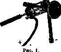
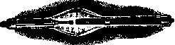
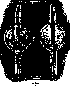
VALVE DEVICES, are used in radiology to prevent the closing phase of the high-voltage current from passing through the X-ray tube. This mainly applies to ion tubes, since electronic tubes do not pass reverse current up to a certain voltage. The passage of reverse current through an ion tube can quickly damage it, because the anticathode, becoming a cathode, will begin to emit electrons (cathode rays), which, striking the tube glass, can melt it due to the thermal effect they cause. Furthermore, the passage of reverse current through an ion tube causes rapid sputtering of the anticathode, since it is made of a substance with a high atomic number (platinum, tungsten). This leads to the absorption of the residual gas in the tube by metal particles, making it so hard that it becomes unfit for work. All valve devices can be divided into 3 groups: 1) a stationary spark gap, 2) a rotating spark gap, and 3) valve tubes.-A stationary spark gap (see Fig. 1) is a glass cylinder with metal bases; in one base there is a hole into which a metal rod, ending in a point and having a screw thread where it passes through the base, is inserted on an insulated handle, allowing the end of the rod to be brought closer to or moved away from the opposite base of the cylinder. It turns out that current easily passes from the rod to the base, but not the other way, because the current density at the point is greater than on the plate, and the current easily overcomes the resistance of the air in this direction. The current is connected to the high-voltage circuit so that the rod is connected by a conductor to the tube cathode, and the plate to the cathode of the high-voltage generator. This device has the disadvantage that it causes noise and the formation of a large amount of nitrogen oxides.-A rotating spark gap (see Fig. 2) consists of two metal plates arranged around a circle, between which a metal wire rotates. This wire is mounted on the extension of the axis of the interrupter motor (D), but is insulated from it and rotates when the interrupter works. As can be seen from Fig. 2, this device is connected in series in the high-voltage circuit, and the wire is set so that at the moment of opening the current, the current passes through the valve gap, and thus through the tube; at the moment of closing, however, the current does not pass through the tube. The length of the plates is chosen so that when the opening stops, the wire does not touch the plates, and therefore only the opening phase passes through the tube. The disadvantage of this device is that the appearance of a spark at the moments of closing and opening the current causes the formation of high-frequency current oscillations, which can damage the tube.-Valve tubes are divided into two large groups according to their principle of operation: 1) ion valve tubes and 2) electronic valve tubes, or kenotrons. The first are built like ion X-ray tubes, but the vacuum in them is less; one of the types of ion X-ray tube regenerators is used to regenerate them. The peculiarity of their construction is that their anode is placed in the depth of a narrow glass appendage of the tube and does not enter the cavity of the tube, while the cathode is placed in the wide part of the tube. Current easily passes from the anode to the cathode, but not the other way, because during reverse current the anode, becoming a cathode, will begin to emit electrons, which will charge the glass of the appendage with negative electricity due to its proximity, while the other electrons will begin to be repelled from it, creating unfavorable conditions for the passage of reverse current. Ion valve tubes differ from each other only in the construction of their electrodes; in some the anode has the shape of a point, the cathode a plate, in others the anode has the shape of a rod, the cathode a spiral, and in others the anode has the shape of a plate, the cathode a tube (see Fig. 3). In order to be able to pass a stronger current, several (2-3) valve tubes are connected in parallel.-Electronic valve tubes, or kenotrons, are built on the model of electronic X-ray tubes (Coolidge). They are airless and have a glowing cathode in the form of a tungsten spiral and an anode in the form of a tantalum plate. They pass current only in one direction (in the direction of the electrons). When using kenotrons, it is necessary to have a source of electricity (accumulator, transformer) for heating the tube cathode in order to obtain electron emission. At present, there are kenotrons that do not pass reverse current up to voltages of 227 kW (see Fig. 4). In recent years, kenotrons have spread strongly in radiotechnology, finding application also in the design of high-voltage current rectifiers. Ion valve tubes and kenotrons are connected to the high-voltage circuit so that their anode is connected to the cathode of the X-ray tube, and the cathode to the cathode of the high-voltage generator.

Related articles
Mentioned in
Cite this page
“Valve Devices.” Soviet Medical Encyclopedia. English translation of Bolshaya Meditsinskaya Entsiklopediya, 1st ed. (Moscow, 1928–1936), ed. N. A. Semashko. https://sovietmedicalencyclopedia.pages.dev/article/valve-devices/