X-Ray Technology
Historical document, translated for reference. It reflects medical knowledge of the 1920s–30s and is not medical advice.
Summary
This article provides an overview of the technical foundations of X-ray equipment as understood in the early 1930s. It details the evolution from early gas-filled X-ray tubes to the modern hot-cathode Coolidge tubes, explaining the physical principles of electron emission, vacuum regulation, and the basic components of an X-ray installation.
Encyclopedia article (1928–1936)
X-RAY TECHNOLOGY. Contents: X-ray tubes... 659; Transformers... 665; Tube operation and requirements for apparatus... 668; Current rectifiers... 670; Apparatus... 671; Methods of measuring rays... 678; Stands... 682; Protection of the patient and personnel from rays... 684; Arrangement of an X-ray department... 684; X-ray production in the USSR... 686. X-ray technology, a department of radiology, encompassing the physical foundations of radiology, the technical design of equipment, the technique of applying X-rays, and safety engineering.
X-ray tubes. X-rays were first obtained by the German physicist Roentgen during experiments with a Crookes tube, which is a glass vessel from which air has been evacuated to 0.001 mm Hg. In shape, it is a tube and carries two fused electrodes: a positive (anode) and a negative (cathode). If corresponding voltages are applied to the electrodes, cathode rays consisting of electrons will depart from the cathode. At the place in the tube where the electrons reach the glass, rays are formed, named X-rays in honor of the one who discovered them. These rays very quickly received great application in medicine.
Comparatively soon, several types of so-called gas or ionic X-ray tubes were proposed. At the present time, they already have historical significance and therefore will be described here only briefly. As can be seen from Fig. 1, they have the shape of a sphere with several appendages. The air is evacuated in the same way as from a Crookes tube. In appendages A and K, electrodes pass—positive and negative. Upon the occurrence of voltages on them, the ions present in the tube are set in motion, each toward the oppositely charged electrode. When ions meet, collisions occur.
At sufficiently high voltages, many electrons are released during this, rushing toward the positively charged anticathode, where X-rays arise. In appendage P, connected to the anode by a wire, a massive metal anticathode is fastened, serving to decelerate the electrons and ions rushing from the cathode. The latter is given the shape of a concave mirror. Particles repelled from it receive directions perpendicular to the surface, as a result of which the electrons must gather on a very small surface of the anticathode, where X-rays are formed. The latter propagate in all possible directions from the anticathode, but a denser part of the rays propagates in a cone with a small angle.
In order to use the rays and protect oneself from stray rays, the anticathode is covered by a special metal cap with holes for the entry of electrons and the exit of rays.
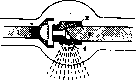
Figure 1. Gas X-ray tube. Figure 2. Methods of adjusting the amount of gas in an X-ray tube: 1—carbon; 2—osmotic.
Finally, the appendage CD contains one of the numerous devices for regulating the gas content of the tube. Experience has shown that even the absorption of gas by sputtered particles of the electrodes or its release during heating while the tube is working already strongly affects the vacuum of the tube and thereby the hardness (penetrating power) of the X-rays being formed. Usually, the tube itself gradually increases the degree of rarefaction (becomes harder), but it also happens the other way around: a tube that has been in use for a long time suddenly becomes too soft. Therefore, many methods of regulating hardness (regeneration) have been devised.

For example (Fig. 2), a palladium tube is fused into an appendage, which can be heated over an alcohol burner. The heated palladium allows hydrogen, alcohol, or illuminating gas vapors to pass inside, and the X-ray tube becomes softer. With the 2nd method, two electrodes are fused into the appendage: a small plate covered with mica or carbon, and a platinum wire. From the appendage CD (Fig. 1), wires B and E, which can be raised and lowered, extend to the anode and cathode of the tube. If the tube has become hard, then the mica is connected to the cathode, and the platinum to the anode, and current is passed. In this process, gas is released from the mica, which lowers the vacuum of the tube. If, however, one connects the platinum to the cathode, it is sputtered under the action of the current, its particles will begin to absorb gas, and the tube will become harder.
The necessity of frequent regeneration of gas tubes, the absence of precise methods for determining the state of the tube, and frequent surprises with the tubes required very great experience when working with them and always left a feeling of uncertainty among the operating personnel. Obviously, all these shortcomings depended on the presence of gas in the tube, which was necessary for the formation of ions and for inducing the cathode to emit electrons. It was necessary to find a way to force the cathode to emit electrons independently of the collisions of positive ions, i.e., practically in an airless space. In connection with this, the idea appeared to use the property of heated bodies to emit their charge in an airless space, discovered by Edison back in the 80s of the 19th century.

It turned out that electron emission could be obtained by heating the cathode. In 1905, tubes with a heated cathode appeared, proposed by Wehnelt and Trenkle. These tubes turned out to be insufficiently powerful and therefore did not gain distribution. Fürstenau in Germany and Langmuir in America also tried to use cathode heating. In Russia, the well-known physicist Prof. P. N. Lebedev attempted to design similar tubes. The first usable tubes with a heated cathode were proposed in 1911 by Lilienfeld. A little later, tubes designed by Coolidge appeared. The latter proved to be the most convenient and simple and therefore completely supplanted the Lilienfeld tubes. In both types of tubes, unlike those described above, the gas is evacuated as much as modern machines allow. The Coolidge tube is shown in Fig. 3.
Figure 3. Coolidge system tube.
From the outside, it has the appearance of a hollow glass sphere with two appendages. The cathode (Fig. 4) consists of a wire spiral made of tungsten or tantalum, placed in a molybdenum cup in such a way that they are not insulated from each other. With such a design, the cup is charged negatively simultaneously with the spiral. The spiral itself can be heated by passing a current through two wires extending from the spiral to the outside. The anticathode is made massive, usually of copper. On the side facing the cathode, it has a small mirror made of refractory metals, e.g., platinum (melting point 3,000°), tungsten, etc.
Figure 4. Figure 5. Figure 4. Diagram of the Coolidge tube: 1—cathode; 2—protective copper sleeve; 3—anticathode; 4—beryllium window for the exit of rays. Figure 5. Diagram of an X-ray installation without a rectifier: P1, P2—primary windings of transformers H and T; S1, S2—secondary windings; G—cathode; C—anticathode. Figure 6. Paths of electrons in the tube: G—cathode spiral; AK—anticathode; S—cathode cup. The operation of the tube occurs in the following way. By heating the cathode spiral, a large number of electrons are forced to be emitted into the practically airless space of the tube. Their quantity depends on the degree of heating of the spiral and, consequently, can easily be regulated with the help of a heating transformer. The speed of the electrons flying out of the spiral is comparatively small. Thus, for example, at a heating temperature of about 2,000°, the average speed of emission is equal to only one ten-thousandth of the speed of light. If one now switches on the main transformer, the spiral and the cathode cup will be under a strong negative voltage and
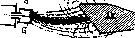
will sharply repel electrons, which are also negatively charged. Conversely, the anticathode, charged positively, will attract them to itself. As a result, the electrons will rush toward the anticathode. The main mass will follow the path indicated by the black stripe in Figure 6. Individual electrons will describe more complex trajectories, marked by the dashed line. These deviations are explained by the mutual repulsion of similarly charged electrons, the size of the spiral emitting the electrons, and finally, the bouncing of electrons off the anticathode itself. True, such electrons will return to the anticathode again. Nevertheless, the force of the impact upon falling will be much less than it would have been during a direct flight. These electrons excite particularly soft X-rays. Thus, by regulating the heating of the spiral with a small transformer (the "heating transformer"), we can easily change the quantity of emitted electrons at will and thereby the quantity of X-rays produced. The same simple regulation using the main high-voltage transformer causes the electrons emitted from the spiral to rush with greater or lesser speed toward the anticathode. The following table clearly shows the speeds developing here:
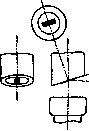
Voltage Speed of electrons (V) Ratio to speed of light 1 VOLT 1 600 25 » 1 3 000 100 » 6 000 10 000 » 60 000 1/500 1/100 1/50 1/5 4/5 In general, it has been established that the speed is proportional to the square root of the potential difference V. Electrons acquire such colossal speeds over short distances between the cathode and anticathode because they are under the influence of a constant attractive force throughout their entire flight, which accelerates their motion. To understand the operation of the tubes, it is extremely important to keep in mind the relationship between the number of electrons emitted into the tube and the time of their travel to the anticathode. If more electrons are emitted per unit of time than are removed from the tube through the anticathode, they will accumulate in the tube and cause great irregularities in operation due to mutual repulsion. Obviously, in this case, there are more electrons in the tube than are needed to maintain the current at a given voltage. According to Ohm's law, the current strength is proportional to the voltage. Therefore, by increasing the voltage at the tube terminals using the main transformer, we will accelerate the flight of the electrons and increase the current strength. If we continue to increase the voltage, we will finally reach the maximum current strength, which will no longer increase despite the increase in voltage. It is not difficult to understand that under these conditions, the spiral emits exactly as many electrons as are absorbed by the anticathode. Now Ohm's law ceases to hold, since when the voltage is increased, the current strength in the tube no longer increases. Such a current is called a saturation current. To further increase the current strength, it is necessary to increase the degree of heating of the spiral. Thus, in Coolidge tubes, it was possible to make the current strength and voltage independent. Each of these properties of the current is independent and easily regulated by the corresponding transformers. Small deviations from this rule occur for two reasons. Firstly, electrons that have accumulated behind the spiral are difficult to extract from there at low voltages. When the voltage is increased, they begin to join the current and thereby increase it. Secondly, if the anticathode is also heated (e.g., in therapy), part of its radiation is absorbed by the spiral, which increases its temperature. An increase in the temperature of the spiral increases the emission of electrons. Types of tubes. Diagnostic tubes. The sharpness of the resulting images will be greater the smaller the focus of radiation. On the other hand, the concentration of a large quantity of rapidly flying electrons in a small part of the anticathode surface causes such an increase in temperature here that even tungsten melts. Depressions and erosions appear on it, which contributes to irregular scattering of the rays. To eliminate this drawback, tubes with two foci and, consequently, two spirals were proposed. A smaller focus (sharp) is used for fluoroscopy and light radiographs; a larger focus (blunt) is intended for high tube loads during instantaneous radiographs. Goetze proposed another solution to the problem. Instead of the commonly used round spirals, he gave them the shape of a strip. The molybdenum cap was changed accordingly. The focus, in turn, stretched out in the form of a strip and sharply increased the surface area. Thanks to this, the generated heat is distributed over a larger area. Goetze's calculation is based on the fact that if one looks along a narrow strip, it appears almost as a point (Figure 7). During radiographs, the anticathode is positioned in such a way that the rays directed at the plate travel at a very acute angle (19°) to the surface of the anticathode, i.e., approximately along the length of the focus. In this case, the sharpness of the image is equal to the sharpness from a reduced focus, as shown in Figure 7. The spirals of modern tubes are in the vast majority constructed according to the Goetze method. For the focus on the anticathode, a platinum or, more often, tungsten mirror is installed. The entire anticathode is not made of tungsten because it emits intense secondary radiation, which has a very harmful effect on the photographic plate. Usually, the material of the anticathode is copper, as it has a low atomic number in the periodic table (copper 29, tungsten 74). In addition, copper is a very good conductor of heat, which is very important, as electrons increase its temperature very strongly upon falling onto the anticathode. To protect against melting, the anticathode is made very massive, and in addition, measures are taken for its cooling. Water cooling is used, in which a glass or metal vessel with water is arranged outside the tube, from where water flows through a special glass tube to the anticathode and cools it. The water itself boils in the process. Therefore, one must take care to leave
an
Figure 7. Focus according to the Goetze method. The rectangle appears as a square. exit for steam from the vessel, because otherwise the vessel will burst, the tube will be wetted by splashes and will be ruined. In the second type of cooling (Figure 3), a ribbed cooler is attached to the anticathode outside the tube, radiating heat with its huge surface. Figure 4 shows the design of protection against scattered X-rays. A dense copper sleeve (e) is placed between the cathode and the anticathode, having a small beryllium window for the exit of the rays. All other X-rays are absorbed by the protective device. Therapeutic tubes are built with the expectation of the greatest possible preservation of the vacuum during operation. For this, the amount of metal in the tubes is reduced, because when heated, it releases gas and thereby changes the vacuum of the tube. In the design of therapeutic tubes, this must be especially kept in mind because the therapy session is conducted for a long time and at voltages much higher than those used in diagnostics. Therefore, heating of the anticathode during therapy is a common occurrence. The anticathode of therapeutic tubes is made entirely of a refractory metal, usually tungsten. Such an anticathode does not require artificial cooling, as it does not melt even at white heat. The heat developing in it is lost through radiation. Tungsten anticathodes, when heated, begin to emit electrons, which can be the cause of the tube's destruction if the high-voltage current is not strictly constant from the cathode to the anticathode, because in the reverse direction of electron flight, the tube cathode is quickly destroyed. The durability of the tube depends on the endurance of the filament. The darkening of the tube sometimes observed is from the sputtering of its metal parts. The wear of the tubes is easy to notice on the anticathode mirror. There, under the influence of temperature, irregularities and erosions appear. The X-rays formed in them are scattered irregularly, i.e., not strictly in a cone. As a result, there are large losses of rays, an increase in Figure 8. Diagram of a metal- exposures and the duration of therapy sessions. Metal tubes. An interesting and promising improvement in X-ray tubes is the lead-coated rubber proposed by the Dutch firm Philips.
(N. Philips) tube made of an alloy of chromium and iron. A feature of such an alloy is its ability to be fused with glass, which ensures the preservation of the vacuum. The design of the tube can be seen in Figures 8 and 9. The anode and cathode are placed, as in previous tubes, in glass sleeves, by which their insulation from each other is achieved. The ends of the cathode and anticathode, i.e., the place of origin and propagation of X-rays, are enclosed in a protective cylinder consisting of three layers. The inner layer is made of chromium iron 3 mm thick. Over
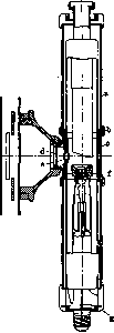
tube: a-bakelite sleeve; b-copper shell; c-lead; c'-filter; e-window for the exit of rays; f-cylinder of chromium iron;

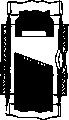
Figure 9. Longitudinal and cross-sections of the protective cylinder of the tube.
inside it is a layer of metallic lead, also 3 mm thick. Finally, the outer layer is a nickel-plated brass shell 1.5 mm thick. The anode and the massive cathode bound this space from above and below. At the ends of the tube, there is also protection made of leaded rubber 25 mm thick. All other parts of the tube are covered by two bakelite cylinders. For the passage of the cone of X-rays, a small window is left in the middle part. According to the designers' idea, all X-rays not entering the cone and not falling into the window should be absorbed by the protective cylinders made of chrome iron, lead, and brass. Reality did not fully justify these expectations. Tubes are made with a power of up to 10 kW. -Tubes for soft rays (Grenz rays). Rays of the transitional (boundary) region between ordinary X-rays and ultraviolet rays were obtained by Holweck, Dauvillier, and Thibaud (1921–27). In medicine, they were first applied by Bucky. Their wavelengths are from 4 to 1 Å (Å-angstrom = 10-8 cm). To obtain very soft X-rays, called 'boundary rays', special small tubes are adapted, which in principle do not differ from ordinary X-ray tubes. Boundary rays arise even at a voltage of 6–12 kV and are absorbed even by ordinary glass, from which the tubes are made. Therefore, at the point of exit of the rays, Lindemann glass is placed, which allows them to pass through. To protect it from the influence of atmospheric air, the Lindemann glass is covered with a special varnish. Transformers. High-voltage currents are obtained by the method of induction or transformation. Adhering to the chronological development of radiology, we will first mention inductor installations, although they are currently almost completely displaced. Current conversion using an inductor has a number of inconveniences. The more important of these are: 1) the curve of the obtained current characterizes it as sharply pulsating, which is very disadvantageous for the operation of the tube; 2) direct current is necessary for the inductor; usually, there is alternating current in cities, so it has to be converted into direct current using a rotary converter (current converter); 3) direct current must be interrupted very often with special interrupters in order to obtain as frequent voltage increases as possible and thereby frequent flashes of the tube; 4) the inductor is very sensitive to voltage fluctuations of the supply network. Furthermore, the complexity of the electrodynamic conditions in the interrupters is inconvenient. All this creates so many difficulties that the appearance of the transformer quickly led to the displacement of inductors. -Transformers are called apparatuses that convert electrical energy of one voltage into electrical energy of another voltage (Fig. 10). A transformer consists of

Figure 10. Diagram of a transformer.
a closed core and two windings of insulated wire. The core is made closed in order to concentrate the lines of force arising in space upon the appearance of current in the primary winding. The resistance to lines of force of particularly advantageous types of iron is approximately 4,000 times less than the resistance of air. According to the law of propagation of action in the direction of least resistance, these lines, having arisen, rush into the core and pass through it along a closed path. In the air, however, due to its resistance, they could only arise partially. The ease of formation and the preservation of the lines of force determine the high coefficient of efficiency of the transformer, i.e., that almost all the energy expended by us in the primary winding is induced and obtained transformed in the secondary. The core is prepared from a special type of iron having low resistance to the passage of lines of force. In relation to the primary winding, the core itself represents, as it were, a secondary winding. Eddy induced currents are formed in it, under the action of which a large amount of heat develops (Joule heat). To eliminate eddy currents, the transformer is constructed from separate plates covered with varnish for insulation from each other. -Joule heat also develops in both windings. The sum of the losses of the core and both windings can be measured at 10–12%. The current introduced into the primary winding does not reach full strength immediately; it needs about 1/1000 sec for this. The induced current in the secondary winding lags somewhat compared to the primary. The phase difference will also be about 1/1000 sec. The period of the alternating current supplied by the station lasts 1/50 sec. Consequently, this time is quite sufficient for the full development of the phases of the secondary circuit. To clarify the action of transformation, one must proceed from the law of conservation of energy. Let us introduce into the primary winding a current of 50 A and 120 V; its power will be 50x120 = 6,000 W. Neglecting inevitable losses, we should expect in the secondary winding the same 6,000 W of transformed current. Let us assume the ratio of the number of turns of the secondary winding to the primary is equal to 1,000. The rings of the secondary winding are connected in series, and therefore each subsequent ring increases the voltage that was in the previous one. An increase in the number of turns by 1,000 times gives a 1,000-fold increase in voltage in the secondary. It will turn out to be equal to 120 kV there. We will find the current strength from the equation: x * 120 = 6,000; x = 0.050 A = 50 mA. The law of conservation of energy requires that the product of the number of amperes and the number of volts of the current remains the same. Therefore, if the voltage increases by several times, the current strength will decrease by the same amount. The number of turns of the primary and secondary windings is usually not the same. The ratio of their number of turns is called the transformation coefficient. If we pass current not into the primary, but into the secondary winding, then in our case we will obtain a transformation coefficient of 1/1000. Then an induced current of low voltage and high strength will flow in the former primary. The resulting transformer will be called a step-down transformer. The technique of calculating the construction of a transformer is very complex. Economy of material, volume, weight, etc., requires the choice of the most advantageous cross-section of the winding wires. For example, for therapy, a current of low strength and high voltage is needed. This means one should use a thinner, but longer winding. Conversely, in diagnostics, the voltage is much lower, and the current strength is much stronger. The thickness and number of turns of the winding change accordingly. The diameter of the winding and the ratio of the number of turns determine the purpose of the apparatus for diagnostics or therapy and thereby impose restrictions on its use. Technical calculation is usually conducted based on ampere-turns, i.e., the product of the number of amperes (A) of current and the number of turns of this winding (N) is calculated. In both windings, such products must be the same, i.e., A1N1=A2N2, where A are amperes, and N is the number of turns. This equality is easily obtained from the equation A1V1=A2V2=W (1), i.e., the power W of each winding is equal to the product of the current strength and its voltage. From here
the ratio of the voltages of the windings is equal to the ratio of the number of turns and the transformation coefficient; this means the transformation coefficient, or by the rule of proportion A1N1=A2N2. The calculation of ampere-turns is necessary when calculating transformer windings, both step-down and step-up. The former are used for heating the cathode of tubes, kenotrons, signal lamps, etc. Here, up to 15 V of voltage is required. Step-up transformers are needed to obtain high-voltage currents: in diagnostics up to 100 kV and in therapy up to 250 kV. Such voltages require special methods of insulation. The greatest voltage difference will obviously be between the ends of the secondary winding, e.g., +50 kV and -50 kV. They must be well insulated. The closer two points are taken, the smaller the voltage difference will be, and the less insulation is needed. For better insulation of the turns, the entire transformer is immersed in a metal tank filled with mineral oil. X-rays in each case of application require different hardness, i.e., different ability to penetrate tissues. Therefore, an X-ray apparatus must have its own keyboard, each key of which provides a precisely predetermined hardness. The latter depends on the voltage of the secondary winding, which in turn depends on the transformation coefficient. By changing it, we will obtain rays of different hardness. It is, of course, possible to change the voltage of the primary winding. Then, with the same transformation coefficient, the voltage of the secondary will decrease accordingly. With the latter method, the current before entering the primary is forced to pass through a greater or lesser resistance (rheostat). Such a method is used more often in filament transformers. With the method of changing the transformation coefficient, the number of turns of the primary coil is changed by switching in a different number of its sections. In the newest apparatuses, so-called autotransformers are widely practiced. Their characteristic feature is that the sec-

Figure 11. Diagram of an autotransformer: JV-supply network; A-autotransformer; S-secondary winding of the main transformer. The secondary winding is, as it were, a part of the primary one. Let us imagine two transformer windings. When current appears in the primary winding, an induced current of the opposite direction will appear in the secondary one. If both these windings are connected electrically, the induction phenomena are preserved and two opposite currents will appear again. The sum of the resulting current will be equal to the difference of the currents that were in the windings before. A reduced current strength will make it possible to use a smaller wire diameter. By making a series of taps from the autotransformer winding, we can change this transformation coefficient. The current obtained in the autotransformer is transmitted to the primary winding of the main transformer. For example, in the apparatuses of the Moscow X-ray Plant, the autotransformer has 26 taps. 13 of them increase the voltage by 1 V each, the rest by 13 V each. In general, the voltage of the autotransformer changes as desired from 80 to 220 V. Correspondingly, the voltage of the primary, and after transformation, the secondary winding of the main transformer changes (Fig. 11).
Operation of the tube and requirements for apparatuses. X-rays arise either as a consequence of changes occurring in the inner electron layers of the atoms constituting the anticathode of the tube, or as a result of the deceleration of flying electrons. In the first case, characteristic rays are obtained, the energy of which is measured by j1 - j2 = hv. Here h is Planck's constant, v is the frequency of oscillations of the emerging X-ray, j1 - j2 is the difference in energy levels of the jumping electrons. Their spectrum is linear, i.e., consisting of separate lines. hv is the quantum of the X-ray. The oscillation frequency v is related to the wavelength λ by the formula vλ = C, where C is the speed of light. The second method, which is more important for us, gives a continuous X-ray spectrum ("white"). This spectrum is characterized by the formula Vλ0 = 12.340. Here V is the voltage in kilovolts, λ is the wavelength in angstroms. The mechanism of ray formation in this case is as follows: a suddenly stopped electron gives up its flight energy. A certain part of this energy forms an X-ray quantum, and in different cases, depending on the conditions of the electron's impact, a greater or lesser part of the electron's energy is converted into radiant energy. The greatest value will be obtained if all its energy is converted into radiant energy. Therefore, the resulting rays will have different frequencies, i.e., they will have a continuous spectrum down to the smallest possible wavelength λ0. A sharp boundary is formed here. Obviously, this boundary depends only on the speed of the electrons' flight, and not on the substance of the anticathode. Calculation shows that the total energy of the continuous spectrum grows in proportion to the square of the voltage V or the fourth power of the electron velocity v, namely j = Ci V2Z. The energy of the electron stream is equal to iV. Dividing the first formula by iV, we find that the efficiency coefficient of the tube is equal to CVZ. Here C is a constant equal to 2.9 · 10-7, V is in kilovolts, Z is the atomic number of the anticathode mirror metal. In general, this coefficient is measured in thousandths. The entire remaining mass of the electron's energy is converted into heat, which heats the anticathode. The formula relating the voltage and the wavelength of the resulting X-ray gives us an indication of the requirements that must be imposed on the apparatus. The wavelength determines the penetrating power of the ray. Therefore, knowing what length of X-rays we need, we can easily determine the kilovoltage necessary for this. For diagnostic purposes, it extends up to 100 kV, for X-ray therapy—up to 250 kV. In addition to simplicity of design and ease of handling, the following requirements must also be imposed on the apparatuses: 1) they must provide current of sufficient strength and voltage for heating the tube. For this, 3-5 amperes and 8-14 volts are needed; 2) the apparatus must provide a powerful high-voltage current. The power requirements of this current depend on the low efficiency coefficient of the tube and the need to impart a very high flight speed to the electrons to excite short-wave rays. Furthermore, for the operation of the tube, a rectified current is important, possibly with minimal pulsation, which does not drop sharply in voltage under heavy loads. The simplest type is an apparatus operating on a half-wave with Coolidge tubes. Its general diagram can be seen in Fig. 5. It consists mainly of a small step-down transformer serving for heating the cathode of the tube and a main high-voltage transformer. Current from the secondary
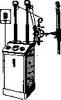
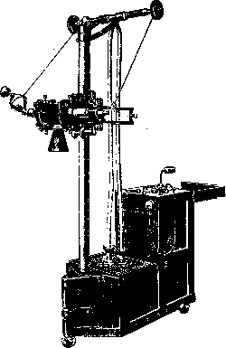
Figure 12. External appearance of the apparatus without a current rectifier.
winding of the main transformer goes directly into the Coolidge X-ray tube. This current is alternating, changing its direction, just like the primary network, for example, 50 times per second. Since in an X-ray tube, as long as the anticathode is not incandescent, current can flow only from the cathode to the anticathode, then out of 100 waves per second, only those whose direction coincides with the direction in the tube will pass. The remaining waves will be blocked by the X-ray tube. Consequently, here the X-ray tube is used as a current rectifier and as an exciter of rays. The current passing through the tube obviously turns out to be pulsating, rectified. Since the milliammeter shows the average value of the current pulses passing through the tube per second, for an individual pulse, the tube is loaded twice as much as a tube operating on rectified current, i.e., if we need to obtain 25 milliamperes from the tube, it must be loaded up to 50 milliamperes. The operating time of the tube can be doubled, since it operates pulsatingly, exactly half of the exposure time. The danger of overheating the anticathode limits the current strength, voltage, and operating time of the tube. The very first signs of the anticathode becoming incandescent are harbingers of the imminent possibility of it emitting electrons and the establishment of a reverse current in the tube, the consequence of which will inevitably be the destruction of the tube. A great many apparatuses of this type have been produced by various firms. They are not suitable for therapy, as they cannot withstand the duration of such work. The external appearance of an apparatus without a rectifier of foreign manufacture is shown in Fig. 12. The Moscow X-ray Plant has assembled such an apparatus for taking pictures in wards and traumatology departments. Maximum voltage 85 kV, load up to 30 mA. External appearance—see Figure 13.

Figure 13. External appearance of the apparatus without a rectifier from the Moscow X-ray Plant; 85 kV, up to 30 mA.
Current rectifiers (valve devices). The listed inconveniences of working without a current rectifier (the impossibility of working on gas tubes, the danger of overheating and destruction of Coolidge tubes) forced the search for convenient methods of rectification. At present, mechanical rectifiers and kenotrons, which have almost replaced them, are used. A mechanical rectifier consists of a cross-piece connected by a shaft to a motor rotating synchronously with the current. Let at some moment the poles of the transformer be positioned as indicated in Fig. 14. Having traced the direction of the conductors, we will see that the negative current is directed to the cathode of the tube, and the positive to the anode. After 1/100 of a second, the poles will change, and the cross-piece will turn by 90°. It is easy to verify that the negative current will again go to the cathode of the tube, and the positive to the anode, and so on. Figure 15 indicates the type of current obtained in this case. The curve (b) should be understood in such a way that the parts of the sine wave going below the abscissa axis are turned by 180° and ended up above it. A rectified, pulsating current was obtained. In reality, the curve is somewhat different. Since there is a certain period of current interruption between the connections of two adjacent contacts of the cross-piece, these parts of the current drop out and only the tops of the sine wave remain. In other words, the tube flashes according to the number of peaks 100 times per second. A full connection does not occur between the rectifier contacts. When they approach each other, the current is conducted with the help of a spark, which requires the expenditure of excess energy and a loss of voltage on the tube of 10-20 kV compared to the transformer. Figure 16 gives the external appearance of an apparatus with a mechanical current rectifier. Kenotrons. The valve properties of X-ray tubes with an incandescent cathode are used for the construction of kenotrons. The latter are high-vacuum tubes
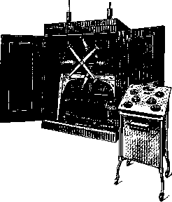
Figure 14. Diagram of a mechanical current rectifier. Figure 15. Current curves: a-before rectification (sine wave); b-after rectification. Figure 16. External appearance.
with a cathode in the form of a current-heated spiral and an anode with a large surface area. To avoid overheating the anode, the filament is made so as not to concentrate electrons at one point on the anode, but on the contrary, to allow them to hit the anode in various places. It is most important that the kenotron, in contrast to the X-ray tube, operates far from reaching saturation current. Thanks to this, the electrons will fly at a low speed and will not excessively heat the anode. It is necessary to keep the cathode heating high enough at all times to ensure a high current intensity, but a low voltage on the kenotron electrodes (about 12-15 V). In the event of obvious heating of the anode or the appearance of a greenish light in the anode part (fluorescence of the glass under the influence of impacts of rapidly moving electrons), it is necessary, to save the kenotron, to either increase the heating of its filament or, if this is impossible, to lower the current intensity in the X-ray tube. The advantage of kenotrons is the absence of irritating noise during operation; when using kenotrons, there are no current interruptions of a mechanical rectifier. The current thus gives a complete curve (Fig. 15 b). The disadvantage is the comparative high cost and the fact that they deteriorate from time to time and have to be replaced. Apparatuses. Single-kenotron apparatuses. In apparatuses without a rectifier, the X-ray tube is forced to block reverse currents itself. This reflects very harmfully on it and shortens its service life. To assist the tube, a kenotron can be placed so that it passes only currents of a positive sign to the anticathode of the tube. Obviously, in this case, currents of the reverse direction
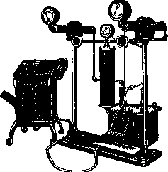
Fig. 17. Single-kenotron apparatus, load up to 150 mA and 100 kVmax.
do not enter the tube and are not used by it. The tube will operate on a half-wave, pulsating, just as without a kenotron. Figure 17 shows the external appearance of such an apparatus, produced by the Moscow X-ray Plant (MRZ). Four-kenotron apparatuses. For full rectification of the current, a system of four kenotrons connected according to the Graetz method (Fig. 18). Solid arrows here show the direction of the current at a certain moment, dashed arrows show the direction of the current after the poles of the transformer have changed. In both cases, the current approaches the tube in the same way. The features of the current of such apparatuses are its continuity and small voltage fluctuations (if there are no fluctuations in the city network). These properties are valuable in diagnostics, especially for instantaneous snapshots. The sinusoidal type of current causes a high content of soft X-rays. The external appearance of the four-kenotron apparatus is shown in Fig. 19. Capacitor installations. It has already been pointed out that the voltages delivered by two-phase apparatuses fluctuate from zero to maximum and back to zero. Accordingly, rays are excited in the tube in flashes—pulsatingly. The hardness of the rays due to voltage fluctuations will constantly change. These features of the current are extremely undesirable in therapy, where the greatest possible homogeneity of rays is needed. A satisfactory solution to the question was apparatuses equipped with capacitors, playing the role of
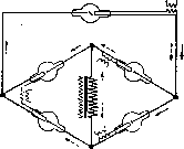
Fig. 18. Diagram of the connection of 4 kenotrons according to the Graetz rule. 74 as if they were reservoirs of electrical energy. In the diagram (Fig. 20) it can be seen that the secondary winding of transformer T is connected by one pole to the outer plates of two capacitors. From
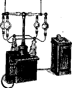
Figure 19. External appearance
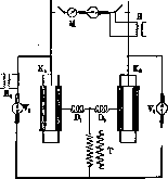
of the four-kenotron apparatus. From the second pole, wires lead to two valve tubes V1 and V2. Whenever this pole is negative, the current from it will charge the right capacitor K2 negatively. In the next phase, the path is open only by valve V1 and capacitor K1 will be charged positively. Obviously, the capacitors will be charged during their phases to the maximum voltage of transformer T. Valve tubes play a double role. Firstly, they allow a charge for each capacitor of only one sign; secondly, they serve as an obstacle to the reverse discharge of the capacitor with the transformer. The current gets the opportunity to flow only through the tube. The advantages of the installation are a relatively little-changing voltage, which is important for approaching the homogeneity of radiation, and the need for transformer insulation half as much as usual, which significantly reduces the cost of the installation. Let, for example, the upper pole change the voltage from +100 kV to -100 kV. Let us ground the lower pole to simplify the calculation and make its voltage equal to zero. Consequently, the voltage difference
between the ends of the transformer Figure 20. Diagram of a capacitor installation.
will not exceed 100 kV and corresponding insulation is required. Obviously, the voltage difference at the ends of the tube will be 100 kV - (-100 kV) = 200 kV. Figure 21 shows the external appearance of the installation. Apparently, the future belongs to these apparatuses.
Universal apparatuses have already appeared, representing a combination of a conventional valve and capacitor apparatus. The use of a capacitor apparatus for snapshots with a high load is not yet applied. In order to keep the voltage from dropping, under modern loads it would be necessary to build colossal capacitors. At their usual size, the current would differ little from the current of a valve apparatus. The constancy of the voltage of a capacitor apparatus requires a high vacuum of the X-ray tube, because otherwise, strong ionization from collisions develops in the tube, threatening the destruction of the tube. In conventional apparatuses, during periods of absence of current or its low voltage, the tube "rests," and ionization decreases sharply. -Apparatus
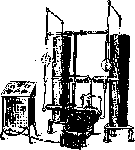
Figure 21. External appearance of the capacitor installation.
of the Moscow X-ray Plant for therapy according to the tripling scheme (Greinacher-Witka). The capacitor installations described above doubled the voltage of the main transformer. According to the Witka scheme (Fig. 22), this voltage can
.
For a certain moment, the voltage at the upper end of the secondary winding of the main transformer has a plus sign. Gradually increasing (sine wave), the transformer voltage will reach the voltage of the capacitors,

[Diagram fragment]
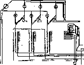
Fig. 22. Tripling scheme: 1-capacitor; 2-transformer; 3-kenotron; 4-X-ray tube.
and from this moment their charging through the kenotrons will begin. In this half-period, the current from the transformer charges both capacitors and powers the tube. The charging of the capacitors will stop as soon as the transformer voltage passes its maximum and begins to decrease. Reverse discharge of the capacitors cannot occur due to the resistance of the kenotrons. Therefore, the current from the capacitors will flow through the tube. When the polarity of the transformer changes, then, as can be seen from the diagram, the tube will be in a circuit in which there are three electromotive forces connected in series: the main transformer and both capacitors. All three forces are approximately equal to each other. Figure 23. Voltage curves in Greinacher-Witka apparatuses.
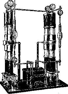
the main transformer is tripled. The installation has a number of design advantages: 1) to obtain 300 kV, a 100 kV transformer is needed; 2) two kenotrons are sufficient; the operation of the latter is facilitated, because on
Figure 24. External appearance of the apparatus of the Moscow X-ray Plant according to the Witka system; up to 220 kVmax and 10 mA.

each falls only 2/3 of the full voltage, and not all, as happens with the doubling system; 3) on each capacitor falls only 1/3 of the voltage, which significantly simplifies the issue of insulating the plates. The advantages of the Witka design are so important that many foreign firms are producing new
Figure 25.
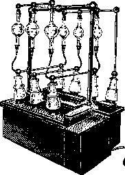
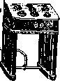
Figure 26. Figure 25. Current curves of a three-phase apparatus: a- before rectification; b- after rectification. Figure 26. Diagram of the connection of 6 kenotrons and an X-ray tube. apparatuses according to his scheme. Figure 23 shows approximate voltage curves for the tripling system. The resulting curve (installation voltage) is drawn with a continuous line (1). The voltages of the transformer (4) and capacitors (2 and 3) are indicated by a dashed line. The apparatus can operate on 2 tubes. Its external appearance is given in Fig. 24. Three-phase apparatus. When taking snapshots of moving organs (heart, stomach), the exposure must last 1/10-1/100 of a second. The current intensity required for this is up to 500 mA. Even greater loads are required for snapshots at large
Figure 27. External appearance of a three-phase apparatus. distances (2-3 m). To obtain such current intensity, it is necessary to use a three-phase current. Figure 25 a shows the voltage curves of all three phases, following one after another at 120°. When rectifying the current, the lower part of the curves (below zero) moves to the top and semi
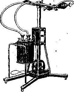
Fig. 21. Appearance of a dental apparatus. Moscow X-ray plant; 62 kV, 10 mA. Figure 25b is referred to. Here, the resultant curve is marked in bold. For three-phase current, 6 valve tubes are needed, connected according to the Graetz rule. The connection diagram is given in Fig. 26. The appearance of the three-phase apparatus is presented in Fig. 27.
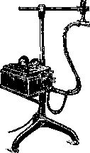
Figure 29. Apparatus for
Bucky boundary rays. Dental apparatus. For radiographs of teeth, jaws, paranasal sinuses, etc., special lightweight apparatuses up to 35-40 kV have been designed. They are usually without a rectifier. High-voltage wires in new apparatuses are insulated so that they are safe to touch. If the wires are not sufficiently insulated and pose a danger, the cathode is grounded and therefore safe; the anode, however, is carefully protected from contact. The Moscow X-ray plant has released such apparatuses. For their appearance, see Figure 28. Portable apparatus. It is often necessary to take a radiograph or perform fluoroscopy at the patient's bedside. For these purposes, small apparatuses are made, which, together with the stand for radiographs and the screen for fluoroscopy, fit into three small suitcases. Their current consumption is so small that they can be powered from any lighting circuit socket. Nevertheless, the power is quite sufficient for the purposes usually required in such cases. Apparatus for obtaining Bucky "boundary rays". To obtain Bucky rays, apparatuses with a power of about 120 W are needed. They provide about 10 mA of current. Consequently, the voltage does not exceed 12 kV. These apparatuses, also without a rectifier, are very small. For the appearance, see Figure 29. Control of the X-ray apparatus. 1. The main switch is usually placed to the side, on the wall. It is two- or three-phase, covered with a case to protect against contact with the wires; it is switched off during breaks in the office's work, during thunderstorms, any special insulation failures of the wiring inside the office, and repairs to the apparatus. 2. The X-ray control table represents the connection in one place of all types of controls for the parts of the X-ray apparatus. It includes: a) switches for the filament transformer of the X-ray tube and kenotrons; b) sliders for the filament rheostats of the X-ray tube and kenotrons; c) switches, coarse and fine, for the autotransformer taps to change the primary voltage of the main transformer; d) a stopwatch (timer) - automatically switching off the current after the expiration of a set time with an accuracy of up to 1/100 sec. In recent years, tables have appeared on which one can set the position for both radiography and fluoroscopy at once. A special switch (Zielbetrieb) is attached to them, usually located at the stand itself and having three contacts: radiograph,
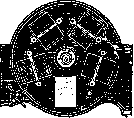
Figure 30. Device for serial radiographs.
zero, fluoroscopy. It is enough to turn the knob to fluoroscopy or radiograph, and the corresponding half of the table, where the necessary conditions have been prepared in advance, will be set in motion. This is a very convenient device. For some organs, serial radiographs are necessary. One of the simple devices is the one indicated in Fig. 30. A round, ray-impermeable board has a 9x12 cm cutout. In addition to this board, there is another one—an aluminum one with five cutouts. Four of them are occupied by cassettes with films, the fifth (in the figure—the bottom one)—by a fluoroscopic screen. The aluminum board rotates. The doctor observes the changes in the organ on the screen (fluoroscopy). At the necessary moments, he places the cassette with the film and takes a radiograph without leaving his place. Then fluoroscopy begins again, and so on. Methods of measuring rays. The first years of the use of X-rays in medicine were overshadowed by a large number of sometimes very serious injuries to the skin of patients and medical personnel. This forced the search for objective methods of measurement. Modern technique for the use of X-rays is already based on strictly scientifically grounded methods. A distinction is made between qualimetry, i.e., spectral differences of rays (their hardness), and quantimetry, i.e., the intensity of irradiation of a unit of surface (quantity of rays). The spectrographic method of qualimetry is based on the property of rays to be reflected from a crystal at an angle characteristic for each wavelength. A very narrow beam of rays is directed for this purpose at a crystal that can rotate. The reflected X-ray beam causes a certain section of the screen to fluoresce. If one starts the rotation from the zero division, the shortest waves will be obtained first. According to the formula FA0= 12.35, it is easy to determine the maximum voltage for this wave, as well as the spectral distribution of the rays of the beam under study. In medicine, this method has not found widespread use. Qualimeters measuring the ability of rays to be absorbed by various metals have gained great fame: the Benoist chromoradiometer and the Wehnelt cryptoradiometer. It is known that thin plates of elements with an atomic weight of 100-150 (e.g., silver) transmit hard and soft X-rays with equal ease. Plates of metals with a lower atomic weight easily transmit hard rays but retard soft ones. The Benoist device is a silver disk, around which twelve plates of aluminum of different thicknesses are arranged. By placing the device between the screen and the tube, one can see that the plates absorb X-rays differently. The number of the plate that absorbs rays equally with the silver one, i.e., glowing on the screen as brightly as the silver one, shows the degree of hardness according to Benoist. Wehnelt arranged aluminum plates in a row. With the help of a slit, a narrow beam of rays is isolated. The lower half of the slit is covered with a silver plate. In the upper one, aluminum plates are changed in turn. There are 15 of them. When the screen brightnesses coincide, the plate number will determine the hardness according to the Wehnelt scale. To determine the quantity of rays, one can also observe some process caused by the action of the rays, which is quantitatively proportional to the intensity of the rays. Such can be the chemical actions of the rays, changes in the conductivity of selenium, or the ionization of gas. Chemical actions are noticed due to the change in color of a number of metal salts under the influence of rays. Holzknecht first proposed his measurer in 1902. The Sabouraud-Noiré method, proposed in 1904, is widely used. They proposed irradiating tablets of a double salt of barium-platinum cyanide. This salt is 4 times less sensitive to rays than the skin. Therefore, the tablets are placed at half the distance between the anticathode and the skin. The intensity of irradiation changes inversely proportional to the square of the distance. Consequently, the tablet will receive 4 times more rays during the session than the skin. Normally, the tablets are light green in color. Under the influence of rays, they lose water of crystallization and acquire a brownish tint. The authors took as a dose the amount of rays sufficient for hair loss 2-3 weeks after irradiation, followed by skin pigmentation. This dose is designated SN and is equal to about 1/4 of the maximum dose. Each set of tablets is provided with a drawing of a normal tablet and one that has changed color from the full
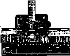
Figure 31. Holzknecht ray dose meter.
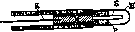
Fig. 32. Diagram of an ionization chamber.
SN dose. A disadvantage of the method is the lack of dose gradations. Therefore, modifications of the device were proposed: in France by Bordier and in Germany by Holzknecht. The latter became widely used in our country, in the USSR. The essence of Holzknecht's improvement (Figure 31) is that only half of a disk of the same composition as in the Sabouraud-Noiré method is irradiated. After irradiation, it is put together with the same half of a disk, but not irradiated. The resulting disk is moved along a scale in such a way that the non-irradiated part moves under a celluloid plate. The latter is unevenly colored with transparent brown paint. Therefore, the non-irradiated part of the disk, passing under the celluloid plate, will gradually change color from normal to dark brown. Up to thirty, so that it is possible to measure doses exceeding SN. These methods have serious disadvantages. Firstly, comparing colors by eye leaves too much to the subjective perception of the doctor. Secondly, with rays from 0.16 to 0.33 Å, due to their selective absorption by barium and platinum, the absorption increases sharply, and therefore the measurement gives inaccurate results. This method still enjoyed general recognition for some time. At the present time, other methods based on the ionization of air by X-rays in ionization chambers (Fig. 32 represents its diagram) have gradually appeared to replace it. The shell H made of celluloid, horn, or light metal isolates a space of about 1 cm3 containing air. Inside is a graphite pin S, connected to a copper pin M
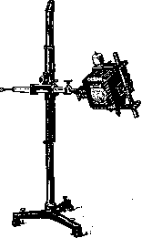
Fig. 34. Stand for radiographs from foreign firms.
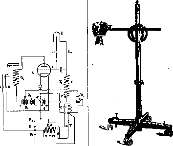
Figure 33.
Diagram of the 'Mecapion' dose meter. If, after moving, it is possible to make both halves of the circle the same color, then one looks at the corresponding number on the scale. The comparison must be made under the light of a carbon electric bulb. Holzknecht units are denoted by the letter H. The Sabouraud-Noiré dose is equal to 5H. The number of divisions on the scale is greater with wire K, leading to the electrometer. The shell is covered with graphite on the inside. Conductors M and K are protected from the action of X-rays by a lead washer B. Shell H is grounded. In a normal state, air is a good insulator. Therefore, the charge of the electrometer spreads along conductors K and M only up to the pin. If X-rays begin to fall on the chamber, then in the chamber, thanks to the occurring ionization, the air becomes a conductor, and the electrometer charge will have the opportunity to reach the shell and then go into the ground. The current strength depends on the degree of ionization of the air, which in turn depends on the degree of absorption and scattering of X-rays by the air of the chamber. Increasing the voltage reduces the absorption of X-rays. Scattering changes very little during this. Therefore, when measuring doses in deep therapy, scattering is of particular importance. At voltages below 150 kV, ionization devices are not entirely independent of the quality of the rays; at higher voltages, they are independent of the wavelength. Figure 35. Stand for radiographs, Moscow X-ray Plant. The small chambers described are used in medicine. Their readings are influenced by the material, the shape of the chamber, the length of the pin, etc. Therefore, preliminary verification with large laboratory-type chambers, free from such influences, is necessary. The principle of measurement consists of
electric charge ,1 L-1
quantity and therefore
requires the same amount of X-rays for discharge, equal to approximately 3R. The time needed for its discharge will be inversely proportional to the quantity of X-rays. If the discharge time is calculated using a stopwatch, i.e., the time needed for the needle to reach zero, then a simple arithmetic calculation will determine the time needed to obtain any dose of X-rays, and the dose of rays obtained in one time or another. Devices of this type are known by the names: iontoquantimeter, ionometer, ionimeter, etc.
The 'Mecapion' by Strauss is now widely used. The pin of its chamber D (Fig. 33) is connected via conductor L1 to the grid G of the amplifying tube V. The shell is connected by conductor L2 to the secondary winding S of transformer Tr. Conductors L1 and L2 are connected to the plates of a capacitor. This capacitor and grid G are charged so strongly by transformer Tr that, despite the anode voltage obtained from a special battery B2, current cannot pass through tube V. If ions are now formed in chamber D under the action of X-rays, the ionization current will discharge both the capacitor and grid G. Current will flow in tube V along the wire to relay R1. The latter, by turning a lever, will close contacts 1 and 2. The result of this will be the simultaneous flashing of a special bulb and a short ring (light and sound signals). The same current reaches electromagnet EM and, with its help, interrupts contact T with a lever, which supported
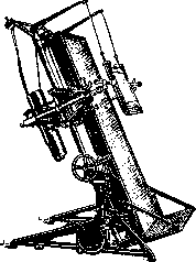
Figure 37. Stand for fluoroscopy from foreign firms.
the presence of current in the primary P of transformer Tr. The interruption of current in the primary winding causes an inductive current in the secondary S. The latter current again charges the capacitor and grid
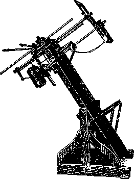
Figure 38. Stand for fluoroscopy, Moscow X-ray Plant.
and everything returns to the initial position. A special device, resembling a clock, is attached to the apparatus. The needle of this 'clock' is set to the required dose of rays. With each flash of the bulb and with the ring, the needle moves one division. Upon reaching zero, it automatically turns off the current of the X-ray apparatus. The light of the bulb and the ring become continuous after this. Stands. In connection with the specifics of the work, stands are built separately for radiographs, fluoroscopy, and therapy. A stand makes it possible for the tube to occupy the most advantageous position with the least difficulty and inconvenience for the patient and ensures the complete immobility of the tube during operation. In addition, it must protect the patient and personnel from contact with high-voltage wires and from X-rays that are not necessary for the set goals. The simplest forms of a stand for radiographs are given in figures 34 and 35. The tube is located in a ray-shielded box. More convenient
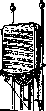
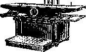
Figure 39. Trochoscope.
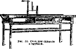
are special tables (Figure 36). Here, the tube easily moves along the length and width of the table and allows several radiographs to be taken without disturbing the patient. The Bucky diaphragm also moves with the tube. There are stands for special radiographs, e.g., of the genitourinary system. They are designed so that it is convenient to perform the necessary manipulations (insertion of a catheter, etc.) on them and immediately take a radiograph. The tube can be mounted both above the table and below it. A special screen makes it possible to perform fluoroscopy of these organs. There are special stands for the accessory nasal sinuses and for stereoscopic radiographs. Fluoroscopy is currently performed with the patient in various positions, i.e., standing, lying down, on the side, etc. Therefore, the stand (Figs. 37 and 38) for fluoroscopy is built so that it can occupy any position together with the patient. These stands make it possible to produce radiographs with the patient in a lying or standing position, which is important for radiographs of shifting organs, accumulation of secretion, effusion, etc. Usually, the tube and the screen are on the same carriage and therefore follow each other, but this has its inconveniences. Horizontal sliding rails are mounted on the carriage, along which the X-ray tube and the screen can move. Thanks to this, the distances between them can be increased to 2-3 m. The latter is important for teleradioscopy and teleradiography. The tube in such a stand is in a casing that lets rays pass only through a small window. The latter is covered with a replaceable filter that absorbs soft X-rays. Modern stands for fluoroscopy are made so that they can also be used as trochoscopes (universal stands). In addition to those described, there are also special stands for fluoroscopy of a lying patient, the so-called trochoscopes (Fig. 39). The tube here is under the table, the screen is on top. Stands for therapy are of the open type, in which the tube is placed in a protective sleeve, e.g., made of lead glass. For stability, the stands are made heavy and
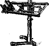
Figure 40. Open stand for therapy.
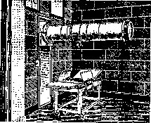
Figure 41. Stand protecting against high-voltage current and scattered X-rays.
therefore they are difficult to move. Such stands (Fig. 40) do not protect against contact with high-voltage wires, and the sleeves usually do not sufficiently absorb scattered X-rays. In recent years, improved devices have appeared that do not have these drawbacks. Among them, the so-called 'cannons' have become most widespread here; they are massive metal structures in which both the high-voltage wires and the X-ray tube are enclosed. When working with them, it is not necessary to cover patients with heavy leaded rubber for protection against scattered rays, and the possibility of contact with high-voltage wires is excluded. Obstacles to their widespread use are their high cost and the need for a spacious room (Fig. 41). Protection of the patient and staff from rays. Work in X-ray rooms, according to Soviet laws, is equated to the most hazardous professions. When discussing the issue of occupational hazards, one should distinguish between the influence of direct, scattered, and secondary rays. Direct rays used in diagnostics can be absorbed by a layer of 2 mm of lead or its equivalent, for example, 6 mm of leaded rubber or 15 mm of lead glass. Secondary radiation is absorbed by a layer of 1 mm of lead. During fluoroscopy, the best protection for the doctor is the patient himself, through whose body, at an average thickness of about 20 cm, only a few percent of the hardest direct rays pass; they can be absorbed by lead glass. Scattered rays present a more serious danger. They exceed direct rays in number by 1.5–2 times, if one considers only the direction of the latter. In general, however, they diverge from the body of the subject in all directions, albeit with less intensity than in the direction of the direct rays. Protection of the radiologist and auxiliary staff from them is the most important task. For this purpose, the fluoroscopic screen is covered with lead glass of at least 30x40 cm and 1.5–2 cm in thickness. Fluoroscopy with a small screen and glass with open diaphragms is very dangerous. Personnel must be at a distance of at least 3 m from the screen and protected by a three-walled screen lined with 3 mm of lead. The fluoroscopy itself should be conducted at a load of 2-4 mA and through a filter of 0.5-1 mm of aluminum. The absence of a filter, as a rule, leads to severe burns in patients. How serious the issue of protection from rays during X-ray therapy is, is shown by the case of temporary amenorrhea occurring in female students who constantly worked in a lecture hall located above a therapeutic X-ray room. With open stands, it is necessary to protect the tube from all sides. It is especially important not to overlook the possibility of rays escaping through the tube cutouts in the protective sleeve or through a gap from a loosely closed filter. Measurements have proven that, depending on the voltage, 3 to 10 times more rays pass through lead glass 1-2 mm thick than through a filter. Therefore, the sleeve must be tested for ray permeability. Finally, one must not lose sight of the possibility of high-voltage wires coming too close to the patient. Organization of an X-ray department. The universally recognized great importance of X-rays in both diagnostics and therapy, the complexity of equipment for modern examination, the important tasks facing radiology as a scientific discipline, as well as occupational hazards—all this requires consideration when discussing the issue of organizing an X-ray department. The department must be able to quickly perform all examinations needed by therapeutic, surgical, and other departments; apparatuses must occupy their designated places and always be ready for work. Auxiliary rooms must be located in the immediate vicinity. The X-ray department is intended not only to satisfy the practical needs of the hospital, but it must also serve as an experimental and educational institute of radiology. The darkroom and the room for personnel servicing X-ray therapy must be protected from rays by lead up to 5 mm thick or an equivalent. From the therapy room, one window opens into the rooms with therapeutic apparatuses, protected by leaded glass 30x40 cm, so that the personnel can see both the beds with patients and the measuring instruments. The darkroom is just as important as other rooms. It must be spacious and well-equipped. The basic rule is to divide it into 2 parts: in one, cassettes are loaded and unloaded; in the other, sequentially—development, washing, fixing, final washing, and drying of films. Light during photographic work is red from ruby glass bulbs located no closer than 1 m from the films. Development and subsequent processes are conveniently performed in vertical tanks covered with lids. Regarding the hygiene of the entire X-ray department, it is necessary to take into account the formation of ozone and nitrogen oxides during the operation of the apparatuses, which are very harmful to health; therefore, good ventilation is needed here. In addition, one must ensure that the entire room can be easily subjected to natural ventilation; for this, wide and high windows are needed. Sunlight should penetrate everywhere as much as possible. Painting the darkroom in dark colors is unnecessary; it is better to paint the walls and ceiling with white paint; they can then be washed more easily. Dust is a serious enemy in an X-ray department, as it contributes to the formation of sparks. Whitewash material, gradually flaking off in tiny particles, constantly supplies dust. In X-ray rooms, high voltage, by electrifying particles and causing them to repel each other, significantly accelerates the formation of dust. While caring for light and air in X-ray rooms during breaks, one should ensure the possibility of completely darkening the room for fluoroscopy. The People's Commissariat of Labor of the USSR developed 'Rules for the Protection of Labor for Workers in X-ray Rooms' (Decree of September 9, 1925, No. 233/389). Some of these rules are set out below. For every worker in the room, there must be at least 30 m3 of air volume, and the air volume in the room must in no case be less than 90 m3. The electrical installation for X-ray rooms must meet the requirements of the 'Safety Rules and Rules for the Construction of Electrical Installations for High and Low Voltage Strong Currents,' which are mandatory according to the decree of the People's Commissariat of Labor of the USSR of November 22, 1924, No. 478/487. No other installations (d'Arsonval currents, quartz lamps, etc.) are permissible in X-ray rooms. -Working hours and vacation. For personnel whose work is connected with continuous presence in an X-ray room and in the sphere of action of X-rays, the duration of the working day is set at 4 hours, and a six-week vacation is granted annually, divided into two parts, each three weeks in duration. For female doctors, feldshers, and nurses working in X-ray rooms and performing direct work during all X-ray diagnostic and X-ray therapeutic procedures throughout the full working day, maternity leave is granted on the same basis as for manual laborers—for 8 weeks before childbirth and 8 weeks after childbirth.
A. Denutovich. X-ray production in the USSR. In pre-war Russia, there was no production of X-ray equipment whatsoever. Only at the Siemens-Halske plant in Leningrad were apparatuses assembled from imported parts; there was no independent manufacturing. During the imperialist war, attempts were made to establish the production of X-ray equipment at the Saxe plant in Moscow and X-ray tubes at the Fedoritsky plant in Leningrad. But these attempts did not yield any serious results, and by the beginning of the reconstruction period, there was neither X-ray production nor personnel for X-ray work in the Union. After the restoration of relations with the West at the end of 1922, the People's Commissariat of Health organized a warehouse for imported X-ray and electro-medical equipment in Moscow. A workshop for repairing apparatuses damaged during transport was organized at the warehouse. In 1923, the workshop began to accept old apparatuses for repair, and a laboratory for manufacturing new ones was organized. In 1924, the laboratory with its workshops was reorganized into the State X-ray Institute. In 1925, thanks to the receipt of some semi-finished products from abroad, the first Soviet X-ray apparatus was released. The workshops at the institute began to gradually recruit personnel and establish the production of X-ray apparatuses. By 1928, production had grown to such an extent that the question of organizing a special plant was raised. Finally, in 1929, on the basis of the workshops of the State X-ray Institute, the Moscow X-ray Plant was founded, which by 1931-32 had completely freed the country from the import of X-ray apparatuses and began to manufacture them from Soviet semi-finished products. Simultaneously and independently of Moscow, X-ray work also developed in Leningrad. In 1926, the Leningrad Medical Supply Trade (Medsnabtorg) organized workshops for medical equipment (MASMO), which also engaged in the repair and modification of X-ray apparatuses. In 1927, the workshops were transferred to the Burevestnik plant, where the first X-ray apparatus was assembled that same year. At the same time, the production of X-ray tubes and kenotrons was being established—initially (1922-29) at the Electro-Vacuum plant in Leningrad, and then it was transferred to the Svetlana plant, which at the present time is the only plant in the Union producing Coolidge-type X-ray tubes and kenotrons. Scientific and technical work on X-ray apparatuses is currently being conducted at the State X-ray Institute in Moscow, the Roentgenological and Radiological Institute in Leningrad, the Kiev Roentgenological Institute, at the Burevestnik plant in Leningrad, and the Moscow X-ray Plant. Work on the application of X-rays in industry and their study is also being conducted in a number of institutes (TsAGI, Institute of Machine Tool Building, Leningrad Physico-Technical Institute, etc.) and factory workshops (e.g., in Odessa), etc. The development of X-ray work in the USSR is clearly visible from the table, which shows the growth of production (in 1926-27 prices) produced by the Moscow X-ray Plant, the Burevestnik plant, and the X-ray department of the Svetlana plant. Years: 1929, 1930, 1931 (2.3 million rubles), 1932 (13.5 million rubles), 1933 (21.3 million rubles). Besides the development of X-ray technical literature, it is necessary to note the development of scientific research and design work, the personnel for which were mainly trained during the first five-year plan. N. Dobrov.
Related articles
Mentioned in
Cite this page
“X-Ray Technology.” Soviet Medical Encyclopedia. English translation of Bolshaya Meditsinskaya Entsiklopediya, 1st ed. (Moscow, 1928–1936), ed. N. A. Semashko. https://sovietmedicalencyclopedia.pages.dev/article/x-ray-technology/