Induction
Historical document, translated for reference. It reflects medical knowledge of the 1920s–30s and is not medical advice.
Summary
This article explains the physical phenomena of electrostatic, electromagnetic, and chemical induction, as well as self-induction. It details the principles of transformers and induction coils, including the role of Foucault currents and Lenz's law in electrical engineering.
Encyclopedia article (1928–1936)
INDUCTION. 1. Electrostatic induction. If one places a conductor A (Fig. 1), charged with positive electricity, near a second conductor B, insulated on a stand, then in the parts of conductor B closest to conductor A, a negative electric charge will appear, and in the more distant parts, a positive charge; furthermore, between the positively and negatively charged parts, a neutral line will pass where there will be no charge. If we remove conductor A, then conductor B becomes neutral; this shows that the quantities of negative and positive electricity that developed on the conductor had the same magnitude. If, in the presence of the electrified conductor A, one touches conductor B with an object connected to the ground, then the positive charge of conductor B goes into the ground, and the negative charge remains despite the connection of the conductor to the ground. This negative charge is held by the positive charge of body A and is thus bound to the position of this body. If, after removing the positive charge from B, one eliminates the connection of B to the ground and removes conductor A or discharges it, then the negative charge that was in region C of conductor B will spread over the entire surface of the conductor and arrange itself in an equilibrium layer. Thus, it is possible to charge a conductor "by influence" without touching it with a charged conductor. This phenomenon is called electrostatic influence or induction. Electrostatic induction is used for accumulating electric charges in electrostatic machines.
2. Electromagnetic induction, a) Let us take two circuits, of which I (Fig. 2) consists of conductor AB and a galvanometer, but has no source of electromotive force, while II consists of conductor CD, a switch K, and a cell E. As long as a constant current flows in circuit II, no current is observed in circuit I. Closing (or strengthening) and opening (or weakening) the current in circuit II cause the appearance of short-lived currents in circuit I. Specifically: upon closing (as well as strengthening) the current in circuit II, a current appears in circuit I that is directed opposite to the current in circuit II (solid arrow in Fig. 2); upon opening (as well as weakening) the current, a current appears in circuit I that is directed in the same direction as in circuit II. This phenomenon, first discovered by Faraday, is called electromagnetic induction. Numerous experiments, conducted under the most diverse conditions, led Faraday to the conclusion that the true reason for the emergence of an induction current is the change in the magnetic field around the conductor.
This is most clearly seen if, instead of a straight wire AB, one takes a coil I connected to a galvanometer, and instead of wire CD, one takes another coil II of smaller diameter included in the cell circuit. Then, as is known, coil II will possess an external magnetic field exactly the same as a linear magnet. By changing the position of this coil relative to coil I, for example, by bringing them closer together or moving them apart, one obtains induction currents in coil I. All these phenomena are especially intensely expressed when a soft iron core is inserted inside coil II, since in this case its magnetic field is many times stronger. Finally, induction currents in coil I can be obtained if one moves an ordinary steel magnet relative to it. The direction of the induction current is determined by the so-called Lenz's law: the induction current always has such a direction that it opposes the process that produces it. For example, if an induction current is excited in a closed wire loop by bringing some pole of a magnet closer to it, then the direction of this induction current will be such that its magnetic field will repel the approaching magnet. Work is expended to overcome this repulsion, at the expense of which the induction current arises. If the induction current had a direction other than that indicated by Lenz's law, i.e., if it did not oppose but facilitated the change by which it is produced, then, once having arisen, the induction current and the change that caused it would continuously strengthen each other and would lead in this way to the creation of work out of nothing. Thus, Lenz's law is a consequence of the law of conservation of energy. A change in the magnetic field entails, first of all, the emergence of an electromotive force of induction in the surrounding conductors. The magnitude of this electromotive force of induction can be found from calculations based on the law of conservation of energy. It turns out that the electromotive force of induction in a certain circuit is equal to the change per unit time in the number of magnetic lines of force encompassed by the circuit. Since, when the number of magnetic lines of force increases, the latter enter the interior of the circuit, and when it decreases, they exit beyond the limits of the circuit, the stated fact can be formulated as follows: the electromotive force of induction is equal to the number of magnetic lines of force crossing the circuit per unit time.
b) Induction currents arising in massive metal masses are called Foucault currents. Due to the low resistance of massive conductors, Foucault currents can reach a very significant magnitude, especially with a rapid change in the magnetic field. The result of their action can be strong heating of the conductors, which is associated with a useless waste of energy, unless, of course, this heating itself is the goal of the process. Thus, one must reckon with the possibility of the emergence of Foucault currents when constructing inductors and transformers, where we are dealing precisely with frequently alternating magnetic fields and large masses of iron (the core). c) Self-induction. An electric current is surrounded by a magnetic field. Any change in the current strength entails a change in its magnetic field, i.e., a change in the number of magnetic lines of force encompassed by the current circuit. But from this, on the basis of the previous, it inevitably follows that any change in the current strength in a conductor causes the appearance of an induction current in this conductor itself. This phenomenon—the inducing of a current in the conductor itself due to a change in the current strength in it—is called self-induction, and the currents arising due to self-induction are called extra-currents. Thus, when closing a current, the cause of the emergence of an extra-current is the strengthening of the magnetic field from zero to a certain constant value. Therefore, according to Lenz's law, the extra-current of closing must be directed so as to weaken the magnetic field of the current, i.e., in the direction opposite to the current in the conductor. Conversely, the extra-current of opening tends to support the waning magnetic field of the opening current and is therefore directed in the same direction as the main current in the conductor. The extra-current of opening usually manifests itself in the form of the well-known spark of opening: the spark in a switch observed when opening a current, the tram spark caused by the departure of the arc from the overhead wire, are results of the extra-current of opening. 3. Chemical induction—see Catalysis.

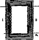
Inductor, induction coil, Ruhmkorff coil, one of the most common devices for current transformation (transformers). The idea of such devices can be clarified with the help of the following simplified scheme. Let there be two windings wound on a common core of soft iron; the primary—with a number of turns n1 and the secondary—with a larger number of turns n2 (Fig. 3). If a variable current is sent into the primary winding, it will excite a variable magnetic field in the core, which in turn will induce a current in the secondary winding. Since in each turn one and the same electromotive force is induced, proportional to the speed of change of the magnetic field, and since all turns are connected in series with each other, the total potential difference V2 induced in the secondary winding will be as many times greater than the potential difference in the primary winding V1 as n2 is greater than n1.
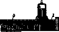
If the current strength in the primary winding is I1, and in the secondary—I2, then the work of the current in the primary and secondary windings in t seconds will be, respectively, I1V1t and I2V2t. According to the law of conservation of energy in the most favorable case, i.e., in the complete absence of losses, I1V1 = I2V2. This means that by as many times as the voltage increases, by the same number of times the current strength decreases. Since the transformation coefficient is equal to several thousand, the current strength in the secondary winding is, generally speaking, very insignificant, as a result of which the secondary winding can be made of very thin wire. All previous reasoning related to the general scheme of a transformer apparatus. The constructive feature of the inductor itself consists in the fact that it has an open, not closed, core. Figure 4 represents a cross-section of a modern large technical inductor. Here K is the core; to avoid useless waste of energy on Foucault currents, it is made not solid, but in the form of a bundle of iron wires or plates covered with shellac to avoid conductive contacts; P is the primary winding in the form of several hundred turns. (Figure 5).
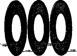
thick wire; R-thick ebonite tube for insulating the primary coil from the secondary; S--secondary coil of several tens of thousands of turns of thin wire in the form of flat sections, separated by insulating layers; 1- either insulating material (for example paraffin) into which the secondary coil is immersed. In Figure 5, the method of winding the secondary coil in the form of flat sections is shown separately. The inductor is usually not powered by alternating but by interrupted current. For this purpose, an interrupter of one design or another is connected in series with the primary coil. The simplest of these is the Wagner and Nef hammer, now used only in small inductors (see Dubois-Reymond's apparatus); in recent times in X-ray technology, so-called mercury-gas interrupters are used almost exclusively. The circuit for connecting the inductor with such an interrupter is shown in Fig. 6. Here R-rheostat with variable resistance,.
N T-interrupter, the most essential part of which is a small turbine immersed in mercury and set in rapid rotation by an electric motor; at the same time, mercury is drawn in by the turbine and ejected in the form of two oppositely directed jets. When these jets hit the contact segments Sx and&2, the current is closed; when they miss, the current is open. C-capacitor, the purpose of which is to minimize the breaking spark in the interrupter. Due to the large self-induction of the primary coil, this spark would be very significant and would adversely affect the operating mode of the inductor. Since when the primary coil is closed and opened, currents of opposite direction are induced in the secondary, the inductor gives an alternating current. The curve of this current is generally sharply asymmetrical. In Fig. 7, the relationship between the current in the primary coil and the potential in the secondary is shown. The increase in current when closing (solid curve Ij) occurs slowly due to the large self-induction of the primary coil. On the contrary, the decrease in current when opening occurs steeply due to the presence of the capacitor. Therefore, the electromotive force induced in the secondary coil (dashed curve^) when opening is significantly greater than when closing. Since for powering X-ray tubes a current of constant direction is necessary, the asymmetry of the voltage curve in the secondary coil is of great importance in X-ray technology. D
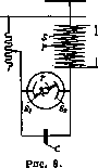
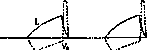
Figure 7.
Indeed, the closing currents can be relatively easily absorbed through valve devices, and only the opening currents remain, rapidly varying in magnitude but constant in direction.
Related articles
Mentioned in
Cite this page
“Induction.” Soviet Medical Encyclopedia. English translation of Bolshaya Meditsinskaya Entsiklopediya, 1st ed. (Moscow, 1928–1936), ed. N. A. Semashko. https://sovietmedicalencyclopedia.pages.dev/article/induction/