Water Lifts
Historical document, translated for reference. It reflects medical knowledge of the 1920s–30s and is not medical advice.
Summary
Water lifts are devices and structures used to raise and move water from lower to higher elevations. This article describes various types including simple manual devices, animal-powered mechanisms, and powered pumps, detailing their construction, operation, and efficiency.
Encyclopedia article (1928–1936)
WATER LIFTS, devices and structures serving to raise and move water from a lower location to a higher one. Water lifts are divided into two groups: 1) those structures and devices which, with the aid of various mechanisms, mechanically move various volumes of water to the required height; 2) mechanisms by means of which water is not only moved and raised through pipes, but also receives the desired pressure, called head. Of the mechanisms of the first group, simple devices deserve attention, such as: buckets, pails, dippers, swinging shovels, Morrel's machine, undershot wheel, tympanum, shadoof, windlass, Persian wheel, noria, chain pump, Shen-Elis pump, Archimedean screw, "mamut" air pump; of the second group: hydraulic ram, hydraulic pulsator, piston, centrifugal and turbine pumps. The simplest water lifts are buckets, pails, etc. in the hands of a person. With a lifting height of 1 m, a worker, in an 8-hour working day, including stops and rest, raises about 40 cubic meters of water. With a greater lifting height, the work of one person becomes less productive. If the lifting height exceeds 2 m, then two workers participate in the lifting, one passing a filled bucket to the one above. In such cases, a bucket with a long handle, or a dipper, which one person can operate, is also used. To facilitate and speed up the lifting of water, a bucket is suspended with the help of a rope, chain, or pole to a swinging beam mounted on a stand, equipped with a counterweight; such a device is called a shadoof. One worker can lift with a shadoof to a height of 1 m in 8 hours up to 55 cubic meters, i.e. 1½ times more than with a simple bucket. If the shadoof is arranged so that the worker can set it in motion by his own weight, then, with a lifting height of up to 3 m, two workers can lift up to 25 cubic meters. Lifting water from deep wells is done by means of a bucket or pail with a rope thrown over a pulley (see Figure 1). For the same purpose serves a windlass, i.e. a horizontal shaft on which a rope with a bucket attached to its end is wound. A windlass is also arranged with two pails, one of which with water is raised while the other, empty, descends (see Figure 2). The category of simple devices for the purpose of irrigating kitchen gardens or pumping water from premises consists of baskets lined inside with troughs. At the points connecting individual troughs there are valves D, E, G for passing water from one trough to the adjacent higher one. This device in one hour
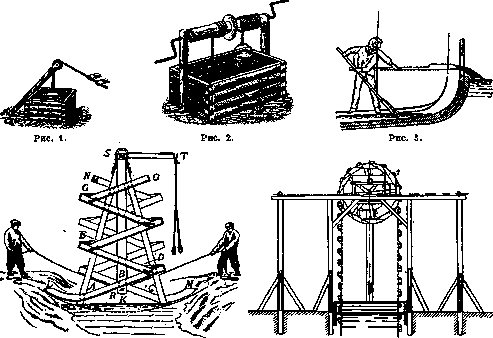
Figure 4.
FIG. 5. Figure 1. Pulley for lifting water. Figure 2. Windlass for two buckets. Figure 3. Dipper for lifting water. Figure 4. Morrel's machine. Figure 5. Persian wheel (front view): 1-handles; 2-bucket. with leather, wooden or metal shovels and dippers (see Figure 3). This category includes Morrel's machine, consisting of zigzag-arranged wooden troughs MN and LBEG0 in a vertical plane, which at the top are connected to a horizontal shaft S. When this device is swung by means of ropes attached to points
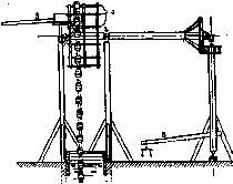
Figure 5a. Persian wheel (side view): 3-trough; 4-spatulas; 5-neck; 6-balance. TRK, water is alternately scooped by the lower ends of the troughs M and L and gradually, in the direction LABD or MSCB and further, moved upward, where it flows into
lifts water to a height of up to 4 m in a quantity of 42 cubic meters (see Figure 4). For lifting water to a height of up to 20 m, devices known as Persian wheel and noria are used, the construction of which is the same: an endless rope is thrown over a drum, to which dippers are attached. To operate the Persian wheel or noria, animals (from 1 to 4) are harnessed to the drive. The use of these devices is widespread in all countries practicing artificial irrigation (see Figures 5, 5a and 6). A device that lifts water by means of a wooden or metal pipe in which an endless chain with attached disks, leather circles, and beads moves, is called a chain, or bead, pump. This pump serves for lifting water up to 5 m. In one hour, four workers can lift to a height of about 2 m up to 72 cubic meters
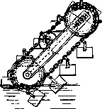
Figure 6. Noria.
of water (see Figure 7). For lifting large quantities of water up to 4.5 m, the so-called Archimedean screw is used, consisting of a wooden or metal drum inside which an Archimedean spiral - a helical surface - rotates, tightly contacting the walls of the drum. The screws are usually set in motion by steam power or wind power. The number of revolutions of the screw per minute is from 5 to 6, and in one revolution the screw lifts about 20 cubic meters of water (see Figure 8). The devices described are set in motion by animal muscle power or a special engine. Water lifts, which are set in motion by the force of the flow of a live stream, include the undershot wheel, equipped with paddles and vessels, or dippers, rigidly attached to the circumference of a wheel rotating on a horizontal shaft. The wheel is installed in channels; the flow of water, acting on the paddles, sets the wheel in motion; usually the diameter of the wheel is about 4.5 m, and it makes 4 revolutions per minute, lifting to a height of 3 meters up to 36 cubic meters of water per minute (see Figure 9). Of the same type is the Roman water lift under the name tympanum, improved by Lafe and consisting of several curved troughs leading from the circumference of the wheel to the center. Water, getting into the trough, when the wheel rotates, rises upward, sliding inside the trough until it reaches the hollow shaft, from where it flows into a collecting discharge trough (see Figures 10 and 11). The air pump, also called pneumatic or "mamut", is a device for lifting water with compressed air through a pipe immersed in a borehole under water to a distance 2-2.25 times greater than the lifting height of the water. Compressed air, entering at the end of the lowered pipe under a pressure slightly greater than the hydrostatic pressure of the water column above this end, will tend to rise up the pipe and therefore will fill the entire water column in the pipe with small bubbles; the water column, having become specifically lighter, will rise up, overflow through the upper edge of the pipe, and then a continuously flowing stream of a mixture of water and air will be established. The coefficient of performance of this pump
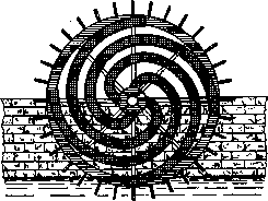
Figure 11. Tympanum.
is very low. Usually water from a borehole is lifted by an air pump into a reservoir arranged in the ground next to the well. "Mamut" air pumps are widely used due to the simplicity
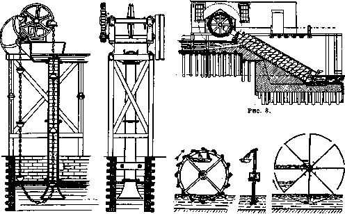
Figure 7.
Figure 9. Figure 10. Figure 7. Chain pump. Figure 8. Archimedean screw. Figure 9. Undershot wheel with buckets. Figure 10. Water-lifting wheel.

of design, maintenance, and ease of observation (see Figure 12).
Belt water lifts (see Figure 13) consist of an endless strip of thick canvas, suspended on a drum so that its lower end is immersed in the well water. When the belt rotates, water rises from the well with the belt by the law of surface tension up to the drum and here is thrown off the belt by centrifugal force into a discharge trough. If to the belt, made of rubber or a thin metal strip, a series of cells of non-corroding metal are attached, then a highly productive water lift is obtained even at low rotation speeds. Thus, for example, with a supply of 2.4 cubic meters Figure 12. Mamut. of water per hour, each cell has a width and depth of 25 mm. Water can be lifted by this lift from a depth of up to 120 m in a quantity of up to 80 cubic meters per hour. However, under such conditions the coefficient of performance is not high. Water lifts of similar action, but having instead of a belt a spiral spring wound around a metal chain, are called water lifts "Shen-Elis" (see Figure 14). It should be noted that these water lifts can be used for lifting both clean well water and for pumping sewage liquids. With abundant water sources, water lifting is often carried out by means of a device inven
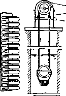
Figure 13. Belt water-
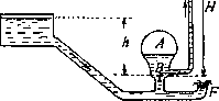
lift. ted by Montgolfier at the end of the 18th century and called a hydraulic ram. The ram (see Figure 15) combines the work of an engine and a pump; it works in impulses from impacts developing from a suddenly closing valve on the path of water movement. The device consists of an air bell A with a valve B, opening from below upward, and with a delivery pipe through which water is supplied to the required height - H. The bell is mounted on a closed box on which an impact valve F is located, opening the hole when lowered down. The box is connected by a pipe to the water source - a reservoir, spring, river, pond, the level of which is located at a certain height h Shen-elis above" the device. The action of the ram consists of the following: water from the source enters the device through the pipe and flows out through the

Figure 14.
Spiral Open stopper or impact valve until the speed of water reaches its maximum and does not close, due to living force, the valve F and, opening valve B, will enter the air bell A. At this moment a certain reverse movement will occur in the box
^Ж
Figure 15. Ram. The flow of water causes a decrease in pressure on the check valve F, which therefore opens. Since the intake of water from the source will be continuous, this phenomenon will repeat itself 60 to 120 times per minute, resulting in the water being raised through the delivery pipe. To start the ram, the valve is first raised and lowered by hand until the device begins to operate automatically. A ram can lift up to 200 liters per minute. If a larger quantity of water needs to be lifted, several rams are installed.
sh
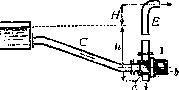
Figure 16. Pressure hydropulser. The hydropulser, invented by Abram (see Figure 16), operates on the principle of a hydraulic ram, but in it the impulse and delivery valves are replaced by a turbine wheel aЪ, which is driven by the water from the source and directs the water alternately into the delivery pipe E (position II) or outward (position I). Sometimes several feed pipes C are included in the turbine wheel casing, and accordingly the performance of the device is increased. Such a hydropulser is called a pressure hydropulser. Similar devices can also be suction types, as shown in Figure 17; here the working water from the feed pipe C enters the delivery pipe E, but at the same time the spent water is drawn through pipe S into the same chamber Eg and, together with the working water, enters the delivery pipe.
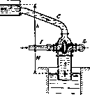
Figure 17. Suction and pressure hydropulser.
Hydropulsers are used for rural water supply, for irrigation, drainage, etc. The listed Water Lifts, in terms of their application for serving populated areas, are divided into 2 categories, one of which (which includes: water wheel, Archimedes' screw, chigir-noria, dipper, Morrel machine) is intended primarily for land irrigation, while the other category (to which the remaining Water Lifts belong) serves, mainly, the water supply of populated areas. Water Lifts of the latter category, in terms of sanitary assessment, can also be divided into two groups, one of which, although more common, must be considered unsatisfactory, since in it the main element used for lifting—the bucket—can contribute to water contamination: these include the shadoof, pulley, and windlass; the other group (e.g., chain, belt, spiral Water Lifts, ram) makes it possible to consider the movement of the lifted water on its path from the point of intake to the point of distribution as sufficiently protected in terms of water quality preservation. The cost of Water Lifts of this group is inaccessible for most of the rural population, and therefore in peasant use, Water Lifts with buckets, which are imperfect from a sanitary point of view, are mainly encountered. It would be quite rational, from a sanitary point of view, to avoid installing such water lifts and replace them with piston pumps, and to make wells covered.
Related articles
Mentioned in
Cite this page
“Water Lifts.” Soviet Medical Encyclopedia. English translation of Bolshaya Meditsinskaya Entsiklopediya, 1st ed. (Moscow, 1928–1936), ed. N. A. Semashko. https://sovietmedicalencyclopedia.pages.dev/article/water-lifts/