Anemometer
Historical document, translated for reference. It reflects medical knowledge of the 1920s–30s and is not medical advice.
Summary
A historical overview of anemometers from the early 20th century, detailing dynamic and static systems used to measure wind speed and air flow in ventilation. The article describes specific instruments like the Richard, Casella, and Robinson anemometers, as well as recording devices known as anemographs.
Encyclopedia article (1928–1936)
ANEMOMETER (from the Greek anemos—wind and metron—measure), an instrument for measuring wind speed, as well as for determining the velocity of air and gases in ventilation ducts, tunnels, flues, etc. Two main systems of anemometers are distinguished: a) dynamic and b) static. The former determine the speed of air movement by the number of revolutions of vane wheels; the latter indicate only the wind pressure on an opposing plate; the wind speed is calculated by the angle of deflection of this plate from its original position. Among dynamic anemometers, which are characterized by high sensitivity to very weak air currents, the instruments of Richard and Casella should be noted. The Richard dynamic anemometer (see Figure 1) consists of a rotating
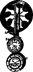
Figure 1. Richard anemometer: A—vane wheel with a lever for engagement; B—stopwatch; C—counter.
wheel with aluminum vanes. If this wheel is placed facing the moving air, the wheel begins to rotate at a speed proportional to the speed of the air movement. The rotation of the wheel is transmitted to the hand of a counter (C), which has a dial divided into 100 divisions. Each division corresponds to 1 meter of the path traveled by the air during its movement. The anemometer is equipped with a stopwatch (B) and a special lever (A), by pressing which the stopwatch and counter are simultaneously put into action. Before starting the measurement of the air movement speed, the anemometer vanes are allowed to develop the proper rotational movement, and only then, by pressing the lever, is the measurement begun. Observation is conducted for 30–60 seconds, after which the lever (A) is pressed in the opposite direction, thereby stopping the movement of the counter hand. By dividing the number of divisions passed by the counter hand by the number of seconds of observation, the speed of air movement in meters per second is obtained. The Casella dynamic anemometer (see Figure 2) is designed on the same principle as the Richard anemometer. The difference between them is as follows: 1) the counter in the Casella anemometer is placed in front of the wheel, while in the Richard anemometer it is located below and serves as a handle for the entire instrument; 2) the Casella anemometer does not have a stopwatch; 3) the Richard anemometer is held in the hands during observations, while the Casella instrument has a stand and can be set down. Structural advantages lie with the Richard anemometer because, thanks to its stopwatch, it allows for very precise marking of the beginning and end of the observation; furthermore, the counter located below does not prevent the air current from freely reaching the anemometer wheel and does not cause those secondary eddy currents observed in the Casella anemometer. Schulz-Fuess anemometers possess high sensitivity to very weak air currents; they are equipped with a clockwork mechanism that brings the anemometer wheel into uniform rotational movement at a speed of exactly 30 meters per minute. If such an operating anemometer is placed in a current of moving air, the rotation speed

Figure 2. Casella anemometer.
of the wheel changes; the difference indicates the speed of the tested air current. Dynamic anemometers of the Combes and Recknagel systems record on the counter not the speed of air movement, but the number of revolutions of the vane wheel. To calculate the speed, a calculation is made according to the formula v = a + bn, where v is the desired speed, a and b are constants determined empirically at the factory that manufactured the instrument, and n is the number of wheel revolutions per second. For high speeds, a constant c is added, and then the formula takes the form v = a + bn + cn². Every precision anemometer must be carefully checked at the factory that manufactured it and have a certificate with a table of corrections. The sensitivity limit of good dynamic anemometers is approximately 0.1 meters per second. The dynamic anemometers described are used mainly for measuring air movement speeds in air ducts, for example, when investigating supply or exhaust ventilation, air heating, etc. At meteorological stations, for
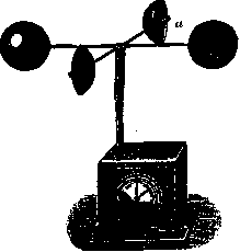
Figure 3. Robinson anemometer.
determining wind speed, the Robinson dynamic anemometer is usually used (see Figure 3), in which the movable vanes have the form of four hollow metal hemispheres (a) mounted on rods. Since the action of the wind on the concave part of the hemispheres is stronger than on the convex part, the hemispheres always rotate in the same direction regardless of the wind direction. The vertical axis of the instrument is connected by means of a gear wheel or electrical wires to a counter, which records the number of revolutions of the vanes or directly the number of meters of the path traveled by the wind. Static anemometers have various forms depending on their construction. The Wolpert static anemometer (see Figure 4) resembles dynamic anemometers in appearance; however, its vane wheel cannot rotate freely because it is equipped with a restraining spring, and it only turns slightly under wind pressure, bending the spring. On the dial, a needle indicates the angle of rotation of the wheel under wind pressure. The speed of air movement is calculated by the formula v = a √n; v is the desired speed, a is a constant, and n is the angle of rotation of the wheel (in degrees). Sometimes the scale has divisions indicating wind speed in meters per second. The Richard static anemometer consists of an aluminum

Figure 4. Wolpert static anemometer.
pendulum, which deviates from the vertical under the influence of the wind and indicates the wind speed in meters on a scale with its end. The instrument has the shape of a weather vane, which easily aligns itself in the direction of the air movement. At Russian meteorological stations, the Wild static anemometer is usually used (see Figure 5), which has the form of a vertically suspended plate. Under wind pressure, the plate (a) deviates from the vertical position, and the angle of deviation is read on an arc-shaped scale (b), and the wind speed is determined by an empirically compiled table. Due to design imperfections, static anemometers provide a less accurate determination of air movement speed than dynamic ones, especially with weak air currents. A significant difference between static and dynamic anemometers is that static ones show the wind speed (pressure) at a given moment, while dynamic ones show the average speed over the observation period. In addition to anemometers, air movements are also measured by rheometers, and very weak air currents (for example, in a room) by the Hill katathermometer.
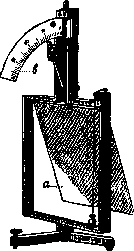
Figure 5. Wild static anemometer.
Anemograph (from the Greek anemos—wind and grapho—I write), a self-recording instrument for registering the speed or direction of the wind. Among anemographs that record wind direction, the most simply constructed is
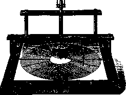
Figure 6. Berger anemoscope.
the Berger anemoscope (see Figure 6): the vertical movable axis of the external weather vane ends below in a lateral writing stylus, which draws a curve on a circular ruled sheet of paper divided into sectors representing the cardinal points; the writing stylus is connected to a clock mechanism, which moves the stylus at a certain speed
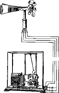
Figure 7. Richard anemosinemo-graph.
in a radial direction and, thus, makes it possible to determine the time and duration of the observation. More advanced Richard instruments—"girouettes anémométriques électriques"—are equipped with a uniformly moving drum on which, by means of electrical transmission, a writing pen marks from 4 to 128 different wind directions. For automatic registration of wind speed, anemographs of a different design are used. Among the advanced instruments recording wind speed per second is the Richard anemosinemo-graph, now adopted at the best meteorological observatories. Its rather complex structure can be seen in Figure 7. Four electrical wires connect the anemometer to the writing instrument, the cylinder of which completes a full revolution within 24 hours. The cylinder is covered with paper, which is ruled with vertical lines representing the hours of the day and horizontal lines representing the wind speed at a given moment. The diagram drawn by the pen is shown in Figure 8. The instrument is constructed in such a way that the anemometer closes an electric circuit and makes a mark on the paper every 25 meters of the path traveled by the wind. For special purposes, an anemograph can be built that makes a mark every meter. The Richard counter-anemometer records on a moving drum the length of the path traveled by the wind during the observation period. By dividing the path length by the time, the average wind speed is obtained. To this type of counter-anemometer belong the instruments of Brusotti, Munro, and others, and for sanitary and technical purposes, the Richard counter-anemometer (see Figure 9) is convenient, which can serve for registering the speed of movement of air and other gases (not harmful to the metal parts of the instrument) in tunnels, pipes, and ducts where the flow of air or gases occurs in a strictly defined direction.
Related articles
Mentioned in
Cite this page
“Anemometer.” Soviet Medical Encyclopedia. English translation of Bolshaya Meditsinskaya Entsiklopediya, 1st ed. (Moscow, 1928–1936), ed. N. A. Semashko. https://sovietmedicalencyclopedia.pages.dev/article/anemometer/