Gas Analysis
Historical document, translated for reference. It reflects medical knowledge of the 1920s–30s and is not medical advice.
Summary
An overview of gas analysis methods and equipment used in medical and physiological research during the 1930s, detailing techniques for collecting, storing, and measuring gas samples such as respiratory air and blood gases.
Encyclopedia article (1928–1936)
GAS ANALYSIS, being one of the branches of analytical chemistry, has the task of determining the composition of gas mixtures, for example, inhaled and exhaled air (see Respiration), blood gases (see), lymph, intestinal gases, etc. (the extensive and extremely important application of gas analysis in technology is left out of consideration here). The first and very essential task in gas analysis is the collection of gas samples for study and the storage of these samples until analysis. Despite the high mobility of gas molecules, the distribution of gases in their mixture is often uneven, especially if certain chemical processes are taking place in the gas environment. Therefore, it is impossible, for example, to take a truly average air sample directly from the chamber of a breathing apparatus (see Gas exchange) at the end of an experiment when a human or animal is still inside it. In this and similar cases, more accurate results are achieved by creating an air current for better mixing and then drawing a sample from it for analysis. On the other hand, the high mobility of gases contains the danger of foreign gas entering the collected sample, such as atmospheric air or air exhaled by the experimenter. One should avoid using long rubber tubes when collecting samples, because rubber easily absorbs gases and, depending on the partial pressure, releases them in one direction or the other. Thus, a thin-walled rubber balloon with a capacity of 150 cubic centimeters, filled with pure nitrogen, after only an hour in atmospheric air contains 1% oxygen, and after 61/2 hours—41/2% (Hempel). Rubber coated with lacquer becomes significantly less permeable to gases. In any case, for collecting and storing more or less significant quantities of gases that are poorly soluble in water, metal or, even better, glass gasometers (see) are usually used. In precise studies for collecting and storing relatively small quantities of gas, clean and dry glass receivers are commonly used, filling them with pure and dry mercury. Figure 1 depicts a very convenient form of receiver. Two three-way stopcocks b and c with capillary tube extensions are sealed to bulb A. The side extensions of the stopcocks are connected by means of thick-walled, well-washed rubber tubes to balloons B and C filled with mercury. Hence, by setting the stopcocks in position 1 (see Figure 1, bottom left), the passages from the balloons to the stopcocks are filled with mercury, carefully expelling the air. Then stopcock b is turned to position 2 and through stopcock c the entire bulb A and stopcock b are filled with mercury (pouring the latter reciprocally into C), right up to the end of tube a. After this, a is connected using a short thick-walled rubber tube, which is also filled with mercury, to the gas sampling point, and, setting stopcock c to position 2, the rate of mercury outflow from balloon A, and consequently of gas collection, is regulated with it as desired. Stopcock c is closed when the mercury level in A reaches the beginning of the discharge tube; stopcock b is then set to position 1 and tube a is filled with mercury. Having closed stopcock b, the connecting rubber tube is removed from tube a and, blocking the opening of tube a with a finger, stopcock b is set to position 3 and mercury is let from B into A so as to fill the lower extension of stopcock b. Having closed b, c is set to position 1, the gas in A is compressed, and c is closed. Thus, the gas remains in the receiver under a pressure slightly greater than atmospheric, and furthermore sealed with mercury at the top and bottom. To take a part of it for analysis, tube a is connected by means of a capillary tube of the appropriate shape and a short thick-walled rubber piece to the analyzer, b is set to position 1, the entire passage to the analyzer is filled with mercury from B, b is turned to position 2, and c to position 1, and the required amount of gas is expelled from the receiver by mercury from C. Having finished the transfer, c is closed and, manipulating stopcock b as indicated above, the gas is again sealed with mercury. With the help of these receivers, the taken sample can be used for a series of analyses and stored for an indefinitely long time. Some investigators collect and even analyze gas over water. This method, introduced (in the 1880s) into the practice of technical analysis by Hempel and into biological practice by Zuntz, and initially widespread, is currently used only in cases where high accuracy is not required. Gas analysis essentially reduces to the precise measurement of the volume of the gas mixture taken for analysis, then to the extraction of its constituent parts separately by suitable absorbers or by combustion, with the measurement of the remaining volume after each removal. Individual gases can be determined, depending on their nature, either directly by absorption (e.g., CO2 or O2) or they must be preliminarily converted by combustion into condensing compounds (e.g., H into water) or absorbing compounds (e.g., CO into CO2). Each time, a change in gas volume occurs, which gives the volume of the desired gas in the first case (upon absorption) directly, and in the second (upon combustion) indirectly, by means of a corresponding calculation. Only nitrogen does not submit to either absorption or combustion and therefore is determined as the final residue. Since the gas volume depends on pressure, temperature, and the tension of water vapor (or another liquid with which the gas is in contact), it is obvious that gas volumes can only be compared after preliminarily reducing them to identical conditions of pressure and temperature, and also excluding the vapor tension of the liquid. Usually, gas volumes are reduced to 0° and 760 mm of pressure, passing from the observed volume to the corrected one according to the formula v0 = vt · (P - p) / 760(1 + kt), where v0 is the volume of dry gas at 0° and 760 mm pressure, vt is the observed
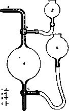
Figure 1. Receiver for collecting and storing gas samples;
volume, P is the barometer (see) reading reduced to 0° observed during gas reading, p is the water vapor tension at the experimental temperature t°, k is the difference between the pressure under which the gas was located during the reading and the observed atmospheric pressure, a is the temperature coefficient of expansion of gases, equal to 1/273 or 0.00366. The classical methodology of volumetric (volumetric) gas analysis was given by Bunsen. To measure gases according to Bunsen, eudiometers are used—straight cylindrical glass tubes sealed at one end (see Figure 2) with platinum wires sealed in at the top and with divisions into millimeters or half-millimeters. Since during preliminary calibration the eudiometer stands head down, and during the experiment—up, a correction for the meniscus (m) must be introduced into the gas volume read during the analysis. For analyses, a small so-called mercury bath (see Figure 2) made of iron is used.

Figure 2. Bunsen eudiometer. In the center of the figure, the eudiometric tube and mercury bath are visible. On the left is the Ruhmkorff coil, which produces a spark that ignites the gas. In the foreground is the tube by means of which the reading of divisions is performed.
or wood with two opposite {long) glass walls. The bath is mounted on a board with a stand carrying a rotating trough for tilting the eudiometer into it when introducing gas or absorbers into the latter. Having carefully filled the eudiometer with mercury so that there are no air bubbles between the mercury and the walls, the opening of the eudiometer is closed with a finger and it is inverted into the bath, where sufficient mercury has already been poured, so that the opening of the eudiometer is under the mercury, and then the finger is removed. Tilting the eudiometer, the gas to be analyzed is introduced into it from the receiver and the eudiometer is set vertically. The entire analysis must be carried out in a special room with the most constant temperature possible. Several hours after setup, when the gas has assumed the ambient temperature, the reading is taken with a tube by the divisions of the eudiometer of the mercury level in the bath and in the eudiometer. This column (h) is subtracted from the barometer, and its length is also corrected to 0°. Often the gas volumes are referred not to 760 mm, but to 1 meter, and then Bunsen's calculation formula will be: v0 = v / (1 + 0.00366t) × (P - h) / 760. Bunsen and many reference books provide a series of tables that facilitate calculations. The reagents necessary for absorption are used in the form of solid pellets of the reagent itself (e.g., KOH) or of papier-mâché impregnated with the corresponding solutions. These pellets are introduced into the eudiometer through the mercury on a platinum wire and pulled back out after absorption. Combustion is accomplished by passing a current from a Rumkorff coil through electrodes soldered into the head of the eudiometer. Hydrogen, oxygen, or explosive gas for combustions are obtained electrolytically in Bunsen apparatuses (see Figure 3). With Bunsen's method 1) absorption proceeds rather slowly, 2) a lot of time passes before the gas assumes the ambient temperature before reading, 3) it is simultaneously necessary to read the barometer and temperature, and 4) to reduce the gas volume to 0° and 760 mm, rather complex calculations are still needed; therefore, a number of researchers constructed apparatuses (analyzers) in which a number of inconveniences were eliminated. This became possible because the technique of manufacturing glass stopcocks reached great perfection and obtaining a stopcock that holds a vacuum does not present great difficulty. With reliable stopcocks, it turned out to be possible to move from the eudiometer and mercury bath to the system of a manometer, i.e., two communicating tubes. One of them with a stopcock at the top (see Figure 4) serves, being precisely calibrated, for measuring the gas volume, and the difference in mercury levels in both tubes gives the pressure of the measured gas, i.e., the value of h in the 1st formula. This eliminates the inconvenience of reading the mercury level in the bath. Furthermore, if the measuring tube is surrounded by a water jacket, then 1) it is easy to maintain a constant temperature of the gas being analyzed and be independent of the room temperature and 2) the establishment of the gas temperature, and consequently the course of the analysis, is extremely accelerated. At the same time, it is also possible to simplify the calculations if the gas is measured either at constant volume and temperature and varying pressure, or at constant pressure and temperature and varying volume. In order not to contaminate the measuring tube (or Hempel gas burette) with absorbers, special working vessels, so-called pipettes filled with liquid or solid absorbers, were introduced into gas analysis practice by Dwyer (Doyère) and then Hempel. Connecting the pipette to the burette (see Figure 4), the gas is transferred from the latter to the former, left there for the time necessary
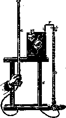
Figure 4. Hempel burette for measuring gas volume. By raising burette a, the gas under analysis is transferred with open stopcock d into Hempel pipette c filled with an absorber of one of the component parts of the gas.
for absorption (for acceleration, it can be shaken), and then transferred back to the burette to measure the residue. A very significant simplification of the technique and calculations of the analysis is the application of the "thermobarometer" principle (Petterson), thanks to which the need for barometer and temperature readings disappears if it is a question of determining the percentage composition of a gas mixture, and when determining the absolute amounts of the component parts, it is necessary to note the standing of the barometer and temperature only once, at the beginning of the analysis. The pressure of the gas under analysis, which is always saturated with water vapor at the temperature of the experiment, was equalized by Petterson in all readings of the analysis with the pressure of some delimited volume of air, also saturated with water vapor, wherein the initial pressure of both the gas under analysis and the delimited volume of air must, of course, be the same. It is most convenient for it to be equal to atmospheric pressure at the beginning of the experiment; then, with constancy of temperature and pressure, the observed changes in the volume of the analyzed mixture directly show the share of participation of each component part in it. The glass tube in which the delimited volume of air is enclosed at the initial atmospheric pressure is called the thermobarometer. Being always in the same water reservoir with the measuring tube, the thermobarometer communicates with the latter differently in different apparatuses: in Hempel—through a mercury manometer (see Figure 5), in Bohr-Tobiesen—through a capillary tube (see Figure 6) with a drop of vaseline oil (differential manometer), and finally, in Haldane—through a manometer made of caustic alkali solution. The apparatus most widely used at present is
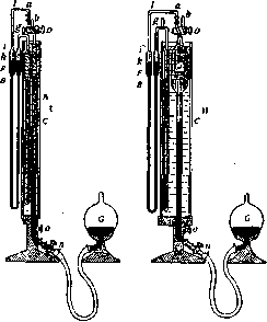
Figure 5. Hempel thermobarometer. The gas under analysis is located in burette A. To the left of it is a tube closed at the bottom (thermobarometer) communicating with the measuring burette through mercury manometer B and stopcock D. The thermobarometer and the measuring tube are located in a common vessel filled with water. Bulb G, filled with mercury, makes it possible to set the mercury in burette A at the desired level.
Haldane's apparatus (see Figure 7). It consists of a thermobarometer TV, measuring tube B, pipette K with caustic alkali solution for carbon dioxide absorption, pipette K1 with alkaline pyrogallol solution for O2 absorption, and combustion pipette G, connected to each other and connected to the atmosphere by a system of capillary tubes and three-way stopcocks. The gas to be analyzed is drawn into tube B through stopcock H2 by lowering mercury bulb N1, and H2 is closed. TV is communicated through tube r3 and stopcock H1 with the atmosphere and simultaneously through h3 with pipette K containing potassium hydroxide solution. This pipette communicates, at the same time, through stopcocks H1 and H3 (H2 is locked) with B. With the help of mercury bulb N1 and alkali bulb N2, the pressure in B is set equal
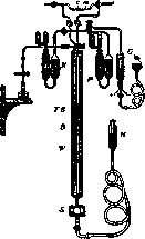
Figure 6. Bohr-Tobiesen apparatus. m - differential manometer; v - droplet of vaseline oil; K and P - vessels with absorbing substances; G - vessel for combustion; N - pressure vessel with mercury.
to atmospheric, wherein the alkali in pipette K must be brought to the mark on capillary tube k1. After this, by turning stopcock H1, the air of TV is separated from the atmosphere and the gas volume in B is read. At each subsequent reading, after absorption of CO2 in K, O2 in P1 and P, or combustion of CO in G, the pressure in B is again set so that the alkali in the capillary stands at the initial mark. Haldane's apparatus makes it possible to perform analyses quickly and accurately. Krogh in the 1900s
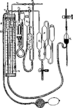
Figure 7. Haldane apparatus.
published a method of gas microanalysis, which, however, is applicable only where it is impossible to have at one's disposal a sufficient amount of gas for ordinary analysis, since the accuracy of the analysis by this method is not high. In addition to the volumetric method considered, other analytical methods—titrimetric and gravimetric—find application in gas analysis, making it possible to indirectly determine gas volumes. The titrimetric method is often used where it is a question of determining a gas contained in a mixture in a small amount (e.g., CO2 in atmospheric or room air). In these cases, a large and furthermore definite volume [through a gas meter or gas clock (see)] is drawn through a titrated absorbing solution, e.g., Ba(OH)2, and after that, by titrating the solution again, the amount of bound gas is established and its percentage content in the mixture is calculated. The gravimetric method, i.e., weighing the receiver with the absorber before and after drawing gas through it, is used only where it is a question of determining large amounts of gas, e.g., the daily amount of carbon dioxide exhaled by humans and animals.
Related articles
Mentioned in
Cite this page
“Gas Analysis.” Soviet Medical Encyclopedia. English translation of Bolshaya Meditsinskaya Entsiklopediya, 1st ed. (Moscow, 1928–1936), ed. N. A. Semashko. https://sovietmedicalencyclopedia.pages.dev/article/gas-analysis/