Ventilation
Historical document, translated for reference. It reflects medical knowledge of the 1920s–30s and is not medical advice.
Summary
This article from the 1928-1936 Soviet Medical Encyclopedia discusses the principles of ventilation in residential and specialized buildings, focusing on natural ventilation methods, their scientific basis, and practical applications.
Encyclopedia article (1928–1936)
VENTILATION. Contents: Ventilation of residential buildings. Natural V..................690 Artificial central V..........693 Artificial local V............698 Ventilation of special purpose rooms. V. hospitals....................698 V. kitchens, laundries and other damp rooms ......................699 Ventilation of laboratories............699 Ventilation of industrial enterprises. Ventilators...................701 Air heating..............703 Air humidification...............704 Air cooling...............705 Air exchange..................705 Local exhausts.................705 Air curtains......................705 Dust control.................707 Fog control................708 Ventilation of mines and quarries...... ... 708 Control and regulation of V.........709 Ventilation (from French ventilation- air exchange) of residential buildings aims to improve the room air spoiled by human respiration, skin evaporation, and household work by replacing it with clean and healthy atmospheric air. Spoiled, 'stale' air adversely affects people's well-being, reduces work capacity, and is characterized by the presence of harmful and foul-smelling organic substances, accumulation of CO2, and increased temperature and humidity. If a room with such spoiled air is not ventilated, a moment may come when the air will no longer be able to sustain life, and people in such conditions will perish, as has repeatedly occurred during the imperialist war with crews of submarines forced to remain underwater for too long. Regarding the causes of the harmful effects of spoiled air on health, there are two theories: one attributes this harmful effect to changes in the chemical composition of the air, the accumulation of harmful compounds of unknown composition (anthropotoxin, kenotoxin, etc.), as well as foul-smelling substances, and points out that the accumulation of these substances parallels the accumulation of CO2 in the spoiled air (Pettenkofer); the other theory holds that the discomfort experienced in air spoiled by humans depends on increased temperature and humidity and is explained by a violation of the body's thermal economy in the direction of retention of animal heat in the body (Flugge). Ventilation of residential buildings.- Natural ventilation. V. is called natural when the replacement of spoiled room air with atmospheric air occurs automatically through pores in building materials, through small cracks in windows and doors, as well as with the help of simple devices and techniques that enhance this natural V.: by opening windows, transoms, using casement windows, hoods, etc. The air permeability of stone walls was first experimentally proven by Pettenkofer in the 1860s through a simple experiment of blowing air through a brick wall. Air passed through the pores of the wall and came out in bubbles through a vessel with water on the other side of the wall. At the same time, the narrow lateral, upper and lower surfaces of the wall were covered with an air-impermeable composition. Pettenkofer, through direct observation, convinced himself that into a room with a capacity of 84 cubic meters, the following amounts of atmospheric air enter through the walls in one hour: with a temperature difference of 20° between the outside and room air - 95 cubic meters, at 19° - 75 cubic meters, at 4° - 22 cubic meters. Consequently, the amount of natural V., i.e., the volume of outside air entering the room in one hour, is greater the colder the atmospheric air is compared to the room air; at the same time, the colder air, being heavier, enters through the pores of building materials in the lower half of the room walls and displaces the lighter room air, forcing it to exit through the pores of the upper half of the walls. Since the weight of 1 cubic meter of air at 0° is heavier than the same volume of air at 20° by 0.089 kg, this difference for a room of 80 cubic meters will be 80 × 0.089 × H/2 = 3.56 kg (H/2 means half the height of the room, which has the shape of a cube, since cold air enters only through the lower half of the walls). Wind pressure on the wall significantly enhances natural ventilation. The forcing power of the wind is proportional to its speed (v), the area of the wall (f) against which it strikes, and the sine of the angle at which it falls on this area. The following formula relates these quantities: P=n.f.v2.sinX, where P is the desired pressure value, n is the air pressure on 1 square meter of surface, f is the size of the wall in square meters, v is the wind speed in meters per second, and X is the angle at which the wind hits the wall. The value of n equals the weight of 1 cubic meter of air at 0° and 760 mm of mercury, divided by the acceleration of motion under the influence of gravitational force g (9.8 m), i.e., 1,293 = -^g- kg. In quantitative terms, natural ventilation is insufficient and irregular, since winds do not blow every day and their direction is variable, while the spoilage of room air by humans, on the contrary, occurs continuously as long as people are in the room. For this reason, it is necessary to enhance natural ventilation. The most common method of enhancing natural V. is to open transoms or windows regularly several times (2-3) a day for a sufficiently long period. In cold weather, such ventilation should be done in the absence of people. Fast and good ventilation of rooms can only be achieved through 'draft', i.e., by opening two windows (or a window and a door) located on opposite walls. If opening one window can double natural ventilation, then a draft from two opposite windows of the same size and in the same time interval will increase it by 6-9 times. In winter, transoms are usually opened instead of windows. The best size for a casement window, or a transom across the entire width of the upper third of the window, which opens into the room at 45° so that when cold air enters the room, it is directed upward first, and not immediately downward. Such transoms are especially recommended to be installed in classrooms, barracks and other rooms that can be ventilated in the absence of people. The simplest devices for enhancing natural ventilation are also transoms in the upper parts of walls, which can be opened and closed as desired; sometimes tin wheels-vanes are inserted in them, sometimes they are closed with flap valves. In some cases, vents are made in the ceiling and connected to a wooden or metal pipe that extends above the roof; to utilize the force of the wind, various types of caps and ventilators are installed on the upper end of such pipes (see Figure 1, 2 and 3). These devices, depending on their design and installation, can supply clean atmospheric air to the room or, conversely, extract spoiled air from the room. On stationary buildings, the useful effect of caps and ventilators is inconsistent and small, as it depends on the whims of the wind. Such devices act more consistently and energetically during the movement of railway cars and steamboats. There have been quite a few unsuccessful attempts, without heating the incoming air, to adapt natural ventilation to function in cold weather in the presence of people, without causing them to feel cold or catch cold. All these attempts amounted to breaking up the air entering the room into the finest streams to accelerate its mixing with room air and warming; for this purpose, air was passed through meshes with small holes or through cloth (engineer Timokhovich). To date, these attempts have not given satisfactory results from a sanitary point of view. It should be mentioned that in recent years in Belgium, a special type of natural ventilation called 'L'aeration horizontale differentielle' (Knapan, 1925) has been proposed, i.e., ventilation with the help of horizontal, rather than vertical, air currents as usual. This type of V. is arranged in some new Belgian schools in the form of small holes in the walls. It has not yet been tested whether this type of ventilation is suitable for our climatic conditions and whether it has justified the hopes placed on it in Belgium. The disadvantages of natural V. are: 1) uncertain and often insufficient amounts of air introduced and 2) the intermittent nature of its operation, due to the impossibility of ventilating a room in the presence of people in cold weather and due to the variability of the factors that move the air. Natural V. finds satisfactory application in small buildings and is completely insufficient for large multi-story buildings. For quantitative accounting of the air entering the room from the atmosphere during natural V., following Pettenkofer's proposal, the so-called 'anthrakometric' method (from anthrax-coal) continues to be used in the following modifications. 1. If there are no people in the room, proceed as follows: measure the capacity of the room in cubic meters; seal visible openings (e.g., ventilation openings, cracks in doors leading to adjacent rooms); evenly arrange stearin candles on the floor, 1-2 for every 20 cubic meters of room volume, light them and leave the room, closing the door tightly behind them.
Candles are allowed to burn for half an hour or an hour; then one enters the room, extinguishes the candles, vigorously mixes the air with cardboard fans, takes three samples of this air in different parts of the room at table height in bottles of about 6 liters, and, plugging them with rubber corks, removes them from the room to determine the CO2 in the air by the Pettenkofer method or the Pettenkofer-Nagorsky method (see Air). Upon leaving, the door is closed, cracks in it are sealed from the outside, and the room is left closed for exactly one hour, counting time from the moment of leaving and closing the door. After an hour, one enters the room again with 3 clean bottles and immediately upon entering closes the door tightly; then the bottles are filled with room air at the same places, plugged, and taken away for a second determination of CO2 in the air. After determining CO2 in the air of the first three samples, the average (p1) is derived from them and expressed in cubic meters; the same is done with the second samples, and the average CO2 content at the end of the experiment is obtained (p2) in cubic meters, where p2 will be less than p1, since during the one hour when the room was left closed after extinguishing the candles, part of the CO2 passed into the atmosphere and its concentration in the room air decreased. To calculate the volume of air that entered the room from the atmosphere during one hour, i.e., the 'magnitude of natural ventilation,' ventilation formulas are used, and most often the following Seidel formula: C = 2.30258. t lg where C is the desired volume of air in cubic meters, entering the room from the atmosphere during an hour; 2.30258 is the empirical coefficient; t is the volume of the room in cubic meters; p1 is the CO2 content in the room at the beginning of the experiment in cubic meters; p2 is the CO2 content at the end of the experiment in cubic meters and a = 0.0005, the content of carbonic acid in cubic meters of air entering the room. 2. Determination of natural V. is somewhat complicated if the sources of CO2 are people present in the room under investigation throughout the entire experiment. In this case, in addition to two series of air samples for determining CO2 by the Pettenkofer method with bottles—the first at the beginning of the experiment, the second at the end—it is also necessary to determine the average CO2 content in the air of the room under investigation for the entire time of the experiment, i.e., during one hour, by drawing air through caustic baryta poured into a Glazovetz-Pettenkofer tube. The results of determinations are usually inserted into the Jacoby formula: Emq v=- (p2 - p1) (p - a) Here V is the desired volume of air, entering the room during one hour, in cubic meters, divided by the volume of the room (this value, according to Hagenbach, is called the 'ventilation coefficient'); E is the volume of the room in cubic meters; v is the observation time in hours; m is the number of people or sources of CO2 in the room; q is the amount of CO2 released by one person (source of CO2) in one hour in cubic meters; K is the CO2 content in the incoming air in cubic meters; K1 is the CO2 content in the room air at the beginning of the experiment in cubic meters; K2 is the same at the end of the experiment in cubic meters; p is the average CO2 content for the entire observation time in cubic meters. One can also use the Jacoby formula in the following reformulated form (K. Lehman): V1 = m - (K2 - K1)E v (p - a) Here V1 is the cubic meters of air entering the room during one hour; E is the volume of the room in cubic meters; v is the duration of observation in hours; m is the volume of CO2 released by people in cubic meters; K1 is the volume in cubic meters of CO2 in 1 cubic meter of air at the beginning; K2 is the volume in cubic meters of CO2 in 1 cubic meter of air at the end; K is the CO2 content in the external air, in cubic meters per 1 cubic meter of air; p is the average CO2 content during the observation time v in cubic meters.—Besides those given, there is a whole series of ventilation formulas (Moren, Schoman, Paris, Lenz, Hagenbach, Kohlrausch, etc.). Artificial central ventilation. In large buildings where people are present throughout the entire working day (e.g., classrooms, public buildings, offices, etc.), the air continuously deteriorates; therefore, the replacement of spoiled air with healthy atmospheric air must also occur continuously and moreover in the presence of people in the room, even in cold weather. In such buildings, which usually have central heating, artificial V. is installed according to the pulsion (supply), and aspiration (exhaust) system, or what is more rational, according to a combined system (simultaneous pulsion and aspiration). In the pulsion system, precisely calculated volumes of heated and humidified atmospheric air are supplied to the room; in the aspiration system, corresponding volumes of spoiled air are removed from it. The combined system of central V. should consist both of supply channels delivering clean air from chambers intended for cleaning the air from street dust,
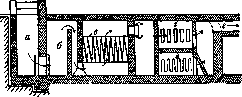
Figure 4. Diagram of artificial ventilation: a-air intake; b-precipitation chamber; c-filters; d-chamber for heating and humidifying air; e-chamber for cooling air; f-internal supply air channel. for its heating and humidification, and of exhaust air channels (see figure 4). Supply channels usually open in rooms in the upper part of the walls, while exhaust channels open in the lower part. The spoiled room air enters the latter, collects into a main channel, through which it is removed either directly upward into the atmosphere (V. with upward draft, see figure 6) or first downward into a horizontal main channel located in the basement floor of the building (V. with downward draft, see figure 5), and then through a high vertical ventilation pipe upward into the atmosphere. Through such a device, the spoiled room air is un- fig Ventilation with draft DOWN replaced downward. A-exhaust pipe; with fresh atmospheric air. B-chamber for heating. n. Such circular movement is usually caused by heating the air in the ventilation chamber with the help of a special heat source (hot water boiler, steam), which must operate independently of heating devices. In some cases, ventilation air is supplied and moved through channels with the help of mechanical force, mostly with the help of blowing and
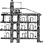
Figure 6. Ventilation with upward draft. A-main exhaust pipe; B-stove chimney.
suction electric fans; sometimes the movement of air, caused by temperature difference, is enhanced with the help of electric fans. Hygienic justifications for calculating the quantities of clean air that need to be introduced into the room (in place of equal quantities of removed spoiled air) were first given by Pettenkofer and obtained experimentally. Based on research on the carbonic acid content of air in residential premises, hospitals, taverns, etc., Pettenkofer established that 1) air containing more than one part CO2 per 1,000 volume parts acts on the organ of smell and on our well-being as spoiled, 'stuffy' air, 2) air containing not more than 0.7 parts CO2 per 1,000 volume parts produces on people the impression of clean air and does not cause those present to feel the need for ventilating the room. Based on the observations presented, Pettenkofer established in the 1860s that air spoiled by human respiration and their skin perspiration contains CO2 more than 1 part per 1,000 and is not suitable for prolonged human stay. This position, despite numerous attempts to change it and even replace it with other criteria, to the present time remains guiding in the calculation of ventilation devices. In practice, for premises that require by their purpose impeccable air from a sanitary standpoint, i.e., for residential apartments, hospitals, etc., the maximum permissible norm of CO2 should be considered 0.7 per 1,000, and in premises for temporary human stay, e.g., in lodging houses, etc., this norm can be lowered to 1 per 1,000. Determination of the 'volume of V.' (Pavlovsky), or 'magnitude of air exchange' (Erismann), can be done based on the CO2 content, humidity, and temperature of the room air. By 'volume of V.' is meant the volume of clean air that needs to be introduced into the room in one hour (and to remove corresponding amounts of spoiled air from it) for proper ventilation.-1. Determination of the volume of V. by CO2 is performed by the following formula L =
in which L = volume of ventilation in cubic meters; K = volume of CO2 exhaled by an adult person in one hour = 22,600 cubic cm; r = maximum permissible content of CO2 in good room air (according to Pettenkofer = 0.7 cubic cm per 1,000 cubic cm of air); and q = content of CO2 in atmospheric air, equal to 0.4 per 1,000. Substituting into the previous formula the numerical designations indicated instead of the letters, we get: L = 0 7104 - 75.33 cubic meters, rounding - 75.5 cubic meters per hour. The coefficient of ventilation, as is evident from the formula, will change with a change in the maximum permissible content of CO2 or the amount of air exhaled by a person in one hour. For example, if the maximum content of CO2 is changed from 0.7 per 1,000 to 1 per 1,000, then we get: L = 0104 = 37.7 cubic meters, rounding - 38 cubic meters per hour. Consequently, depending on the lowering of the standard determining air purity by CO2 from only 0.7 to 1.0 per 1,000, the volume of ventilation, i.e., the inflow of atmospheric air, will be halved. For this reason, most hygienists, as a rule, indicate the standard for CO2 as 0.7 per 1,000 and for air exchange as 75.5 cubic meters (Pettenkofer, Rubner, Dobroslavin, Erisman, etc.), and only a few recognize the standard for CO2 as 1 per 1,000 and the coefficient of ventilation as 38 cubic meters (Flügge and some others). Practical engineers, on the contrary, tend toward the latter standard for gas exchange, since with a decrease in the volume of air supplied, the costs for the installation and operation of central ventilation are reduced; sometimes they combine these standards. -2. The volume of ventilation can also be determined by the temperature of the room air, since, according to Flügge, the main role in the unfavorable effect of 'stale' air on our well-being is played by the increase in temperature and humidity of the room air, and not changes in its chemical composition. Ritschel proposed the following formula for calculating the volume of ventilation by temperature: i = W. (1 + at) 8;309 (t_ti) in Ritschel's formula L = volume of ventilation; W = amount of heat generated in the room in one hour (by people, heating, etc.); a = coefficient of expansion of gases = 0.00367; t = maximum temperature of air in the room; tx = temperature of the incoming air. Since the effect of air temperature on our well-being to a high degree also depends on its humidity and movement, the temperature standard cannot be constant; the same drawback is also inherent in the magnitude of W, therefore the volumes of ventilation calculated by temperature also do not correspond to the actual needs. -3. Calculation of the volume of ventilation by air humidity is carried out according to the following formula: L = In the formula L = volume of ventilation; Ch = amount of water vapor in grams exhaled by an adult person in one hour; gL = content of vapor in the incoming air; g2 = permissible amount of water vapor in room air. Using this formula, one usually obtains even larger volumes of ventilation than when calculating by carbon dioxide, and less constant ones. From a hygienic point of view, the best method for determining the amount of air exchange in artificial ventilation still remains determination by CO2, and therefore it is more often applied in practice. In special cases - for ventilation of rooms with very high temperature, for example, in boiler rooms, or with very high humidity, for example, in laundries, in humid departments in factories, etc. - formulas with limiting temperatures and humidity are also used for calculating air exchange. The doctrine of effective temperatures, which combines temperature, humidity, and air movement under the control of good well-being, or 'comfort,' will, it is to be hoped, give greater scientific and practical stability to the calculations of air exchange for central ventilation. When arranging artificial ventilation in residential and other premises, engineers, using Pettenkofer's standard, supply the following volumes in cubic meters per person per hour (Moren, Ritschel, Pavlovsky, etc.): hospital wards for infectious diseases - 100, for non-infectious - 60-75, for children - 35, classrooms for children up to 10 years - 12-20, over 10 years - 20-30, barracks and prisons - 30-50, public places, offices - 20-40, auditoriums, concert halls, theaters - 20-30, workshops - 70, lavatories - 60-100, kitchens per 1 hearth - 200-300. Experience has shown that ventilation in the indicated dimensions has a beneficial effect on patients, students, soldiers, prisoners, and employees. The figures given indicate how much clean air needs to be introduced per 1 person per hour; therefore, if a room consists of wards or cells for 1 person and if their minimum size is equal to the ventilation coefficient, i.e., 75.5 cubic meters, then it is sufficient to exchange the air once per hour to maintain its necessary purity. In other words, under these conditions, the space occupied by one person, called the 'air cube,' or 'cubage,' and the 'ventilation coefficient' are equal to each other. In rooms designated for many people, the cubage per person can be reduced if the air exchange is accelerated, i.e., if it is carried out more than once per hour. This reduces, without harm to health, the volume of the room, and consequently, the costs of constructing the entire building. Since in practice the speed of exchange of ventilation air usually does not exceed 2 revolutions per hour, the 'air cube' usually equals the 'ventilation coefficient,' i.e., 75.5 cubic meters divided by 2, i.e., about 40 cubic meters per person. For premises in which the number of occupants is uncertain and variable, the amount of air exchange cannot be calculated per 1 person per hour; in such cases, the volumes of incoming air are expressed in multiples of the volume of the premises: for moderately occupied premises, a single exchange is sufficient, for more occupied premises - double, and for premises having special sources of air contamination (kitchens, chemical laboratories, closets) - up to fivefold. Taking into account that the 'air cube' (cubage) is obtained by dividing the above air exchange volumes by two, the following cubages (in cubic meters) have been adopted: for schools 6-15, barracks and prisons 15-25, workshops 35, hospitals (general wards) 30-50. In the ordinary sense, cubage is defined as the quotient obtained by dividing the capacity of the room by the number of people present or living in it, without indication of the speed of air exchange. Artificial ventilation should function continuously in both warm and cold seasons of the year, regardless of heating, and should have good regulation. Local artificial ventilation is arranged in buildings having local, not central heating, i.e., heated by fireplaces and stoves of various systems. Heating appliances in these cases are adapted for drawing out foul air or for supplying atmospheric air to the room. Thus, through a Dutch stove during one hour of burning, as much air is drawn out of the room as is required for 1 person, and through a fireplace - for 10 people. If outdoor air is introduced between the wall of the Dutch stove and its casing, it will ventilate the room as it heats up. The ventilation stove of M. Favorsky should also be mentioned, which is heated by a kerosene lamp and supplies warm and dry air to the room. In some cases, ventilation fireplaces of the Douglas-Galton system with the supply of fresh air are good. Electric fans also work reliably. Local ventilation with thermal draft is inferior to central ventilation in many respects: it supplies an insufficient amount of air, does not humidify it, often imparts an unpleasant and irritating smell to the nose and throat to the supplied air due to the charring of dust, and is inextricably linked with heating. Some authors do not consider local ventilation as artificial, but view it as a method of enhancing natural ventilation (Pomortsev).
G. Khlopin. Ventilation of special-purpose premises. - Ventilation of hospitals. The question of the most suitable system of V. for hospitals has not yet been fully satisfactorily resolved. Complex and expensive mechanical ventilation installations in hospitals, which were built in Germany during the period 1900-1914, at great expense, are now considered by many to be excessive. German authorities in hospital construction currently consider that the best for hospital wards is natural V., with the additional introduction of fresh clean air from outside through doors and windows; such V. should be preferred to central (Alter). In Germany, local V., ensuring correct and constant intake of clean air and removal of contaminated air separately for each ward, is considered the most suitable; in this case, it is recommended to avoid the installation of a network of ducts, which collect dust and serve as conductors for the spread of infection. 69 This view on V. of hospitals exists not only in Germany. In the U.S.S.R. it is also now being implemented. Recently, the construction of a large and richly equipped hospital in memory of war participants (The Wisconsin General Hospital) has been completed. The V. of the wards of this hospital is carried out by introducing fresh air from outside through specially designed devices in the windows, directing the air toward the ceiling to avoid the effect of cold air currents on patients. Artificial V. in hospitals in America and Germany is considered necessary to install only in special premises: in toilets, bathrooms, laundries, kitchens, etc. In toilets and bathrooms, only exhaust ventilation ducts are installed; in these premises, reduced pressure is maintained, due to which a constant air current is established from the wards and corridors into the toilets; this device prevents air from penetrating from the toilets into other premises. For toilets and bathrooms, 3-5 air changes are recommended. Ventilation of kitchens, laundries and other damp premises. V. of steam and ordinary kitchens and other premises connected with kitchens, e.g., rooms for washing dishes, food distribution, is carried out by means of artificial supply-exhaust V., with preheated to +20° fresh air being introduced into the room by a fan. When introducing air into the room, attention is paid to its correct distribution in the room, especially in those places where water vapor forms. The maximum air exchange for steam kitchens is usually 15-fold (Göttinger), in dishwashing, distribution rooms - 5-fold the volume of the corresponding premises. V. and dehumidification of steam laundries are also carried out by means of artificial supply-exhaust V. Heated outdoor air enters the room through an opening in the wall located above the washing machines, and exits through an opening in the opposite wall under the ceiling (Göttinger). The usual method for removing fog from premises - opening windows or doors - does not achieve the goal, as the inflow of cold air further intensifies the condensation of water vapor in the air. In such cases, it is necessary to introduce dry heated air or place in places where fog forms a sufficient number of steam heating devices, which, by heating the air, do not allow condensation of water vapor or contribute to the disappearance of the already formed fog. Ventilation of laboratories. V. of chemical laboratories aims at the rapid and complete removal of harmful gases, vapors, fumes and dust formed during chemical work. For this purpose, exhaust hoods are installed in laboratories, in which all chemical work accompanied by the release of harmful gases, vapors, etc. is carried out. In addition to exhaust hoods, artificial general V. is also installed in well-equipped laboratories. It has been established that an exhaust hood works reliably only if there is rapid and uniform air movement inside it towards the exhaust opening. The speed of this movement should be higher than 0.15 m/sec. (Verkhovsky). The desired speed in exhaust hoods is achieved by draft based on air heating or the action of mechanical fans. In the first case, the exhaust openings, upper and lower, are connected to the highest possible outlet duct, in which the air is artificially heated (e.g., by gas burners), or the wide outlet ducts of the exhaust hood are led into the firebox of a specially constructed furnace. The best draft in exhaust hoods is achieved with the help of mechanical fans, which mostly run on electricity. The advantages of such draft: independence from outdoor temperature, constancy and convenience of operation, absence of long exhaust ducts. For work with especially harmful substances, it is recommended to install exhaust hoods only with electric draft, as operating constantly. Any laboratory exhaust hood can be adapted for work with poisonous gases by installing an exhaust in one of the side walls. Two exhaust openings must be made: one with the lower edge above the level of the hood table for extracting heavy gases, and the second closer to the upper wall of the hood for light gases and vapors. The power of the fans should be such that when opening the farthest door of the hood, the speed of air movement against this door equals about 1 l/sec. (Khlopin and Prokofiev). When arranging general V. of laboratories, the following two circumstances are taken into account: 1) there is a large amount of water vapor and harmful gases in the air of laboratories; to obtain sufficient dilution of these impurities, especially large air exchange is necessary, up to 10-20 times per hour; 2) the specific weight of air in laboratories is usually somewhat greater than that of external air due to the admixture of heavy vapors and gases during chemical work; therefore, it is advisable to remove the spoiled air from the laboratory through ventilation openings located not higher than human height, and to introduce fresh air from above under the ceiling through as many openings as possible. In summer, the incoming air is advisable to cool before entering the room, and in winter - to heat (Girsh). Whether there should be increased or decreased pressure in laboratories is decided in each individual case separately, depending on local conditions. The most perfect ventilation installation in laboratories has approximately the following arrangement. Fresh air first passes through an apparatus for washing, cooling and cleaning. In the latter, the air passes through a layer of coke, constantly irrigated with cold water. In the next layer, the air is freed from water droplets carried over from the first layer of the filter. Further, the air is directed to the heater, where it is heated, and its relative humidity is brought to the corresponding level. The air processed in this way enters the room through a large number of funnel-shaped distributors hanging from the ceiling and arranged in such a way as to allow uniform distribution of clean air throughout the room. The introduction of fresh air must be carried out through a large number of openings located throughout the room, since otherwise, due to the large exchange, unpleasant air currents may occur. Such an installation is described as working well in summer and winter. v. Yakovenko. Ventilation of industrial enterprises. V. of industrial enterprises differs from V. of residential premises both in its tasks and in its methods of implementation. Industrial V. aims not only at exchanging air spoiled by human respiration, but also at eliminating specific hazards associated with a given production; moreover, V. of industrial establishments often has not only sanitary but also purely production significance (e.g., in the textile, in the mining industry). Among the hazards to be removed by V. are: industrial dust, poisons, as well as fumes and mists, both purely aqueous and containing impurities (e.g., acid impurities in pickling departments). The listed specific hazards are most rationally removed directly from their place of release by means of local exhausts (exhausters), so that the exhaust is placed between the place of release and the worker. But since this is not always possible to achieve completely, the general air exchange of industrial premises, achievable by supply-exhaust ventilation, also plays a role in the removal of hazards. Means of moving air masses. In industrial V., there is movement of large masses of air and in specific volumes corresponding to the given conditions. Natural V. or primitive artificial V. by means of deflectors, open windows and skylights, although often found in existing industrial establishments, cannot be considered a rational method of industrial V., since by this method it is impossible to ensure a quantitatively precisely determined air exchange. Therefore, these ventilation methods can, as a rule, only serve as auxiliary means to mechanical V.
For mechanical ventilation, centrifugal and screw fans are mainly used; to a lesser extent, steam-jet, water-jet, and air-jet devices are used. Fans, by moving masses of air, must overcome a series of resistances. These resistances consist of the following: resistance from friction against the walls of pipes and ducts through which the air moves; local resistances that occur when the speed and direction of movement change—at turns, in expansions and contractions of ducts, in gratings, in valves, dampers, etc. To overcome these resistances, the fan must force the air under a certain pressure if it is blowing air into the ventilation system (supply ventilation) or extracting air with a certain vacuum (exhaust ventilation). This pressure and vacuum are measured by a manometer and are expressed in mm of water column (1 mm of water column corresponds to a pressure of 1 kg per 1 sq. m). In cases where the ventilation system is a network of ducts, in which the sum of resistances is usually expressed in several tens of mm of water column, centrifugal fans are used. Screw fans, which provide a small head (usually 10-20 mm of water column), are used where there are few local resistances, mainly in the absence of air duct networks, when removing air directly from a room to the outside or when supplying fresh air directly into a room. The energy consumption required for the operation of fans is greater the larger the volumes of air the fan moves and the greater the head. If we denote the second volume of air in cubic meters as L, and the pressure in mm of water column (or in kg per 1 sq. m) as p, then the theoretical work of moving the air A (in kg·m) is expressed by the formula: A = L·p kg·m/sec. The theoretical power required for this, in horsepower N, is expressed by the formula: N = L·p/75. In reality, the energy consumption and required power are significantly greater: as air passes through the fan, very intense vortex movements occur inside it, for which a very significant part of the energy is wasted (from 40 to 75%, and under unfavorable conditions even more). The efficiency of fans η, i.e., the part of usefully spent energy out of the total energy consumption, for centrifugal fans, under normal operating conditions, ranges from 0.7 for the largest to 0.3 for small ones; for existing screw fans, the efficiency is below 0.3-0.2. Introducing the efficiency, we have the formula for the actual required power: N = L·p/75η. If a centrifugal fan, designed to work with significant resistances, is started to work without resistances (for example, to remove air directly from a room to the outside), it will still consume a significant amount of energy on vortex movements inside the fan itself, and its efficiency will be very small. Therefore, for small resistances, screw fans are more applicable. It should be noted that recently, thanks to the application of precise aerodynamic calculations to the design of screw fans, it has been possible to significantly increase both their efficiency and the head obtained. Resistances to the movement of air in the system, for a given cross-section of ducts, are proportional to the squares of the speed; at the same speed, the resistances per unit length of duct are greater the smaller the cross-section of the duct; when the direction of movement changes (at turns), the resistances are greater the sharper the turns; resistances for a certain type of movement change (for example, turning a pipe at a certain angle) are proportional to the speed of movement. Where there are many sharp turns without rounding in the system, a very significant part of the total head is wasted in such local resistances—up to 80-90% or even more. Therefore, when installing industrial ventilation, sharp unrounded turns and branches should be avoided as much as possible; they should be made with a radius of curvature of at least 5 pipe diameters, so that the turn is not accompanied by a loss of head. For supply-exhaust ventilation, the air replacing the removed air must be preheated in cold weather; in hot weather, it sometimes needs to be cooled; in many cases, the air entering factory premises must be humidified; if it is not sufficiently clean, it must be freed from dust, and sometimes from impurities of various gases. Air heating is accomplished in calorifiers by means of cast-iron radiators, iron pipes, or plate devices heated by steam. Radiators are either ordinary ones, as for water or steam heating of residential premises, or special ones for calorifiers, having a rhombic cross-section; thanks to this, in batteries composed of several rows of rhombic elements, the passages between elements are easily accessible for cleaning. Among tubular air heaters, Stürtevants' calorifiers are widely used. They consist of batteries of iron tubes enclosed in a casing, with an external diameter of 33 mm, with clearances between tubes of 5 mm; steam flows through the tubes—from 1 to 5 absolute atmospheres pressure; air is blown through between the tubes by a fan and is heated. Plate air heaters by Prof. Junckers are characterized by great compactness. They consist of iron or copper tubes with frequently attached iron or copper plates; the entire system is covered with tin if the calorifier is made of copper, or with zinc if the material is iron. Thanks to this, a metallic connection is obtained between the tubes and plates, and the heat received by the copper tubes from the steam passing through them is well transferred to the plates. The faster the air is blown through the heating devices, the greater their heat output, but also the greater the resistance to air passing through them. For example, the heat output and resistances in a Stürtevant calorifier consisting of 4 rows of tubes will be as follows [for the average air temperature entering the calorifier = 0°; in the 1st column of the table is the speed of air passage in the narrowest clearance between tubes; in the 2nd column—the amount of heat transferred by 1 sq. m of the surface of the calorifier tubes to the air per each 1° difference between the steam temperature and the average air temperature in the calorifier; in the 3rd column—the loss of head (resistance) when air passes through the calorifier]. Air passage speed Amount of heat transferred by 1 sq. m of tube surface Resistance (in mm of water column) 1 m/sec 5 » 10 » 15 » 20 » 21.0 cal. 54.4 » 81.9 » 104.0 » 123.3 » 0.18 3.15 10.70 22.00 36.60 Humidification of air in industrial ventilation plays a major role, and in some productions (spinning and weaving departments of textile factories) it is absolutely necessary. For example, fine grades of yarn can only be obtained with significant air humidity. The following relative humidity (in %) is considered most favorable: in weaving departments 70-80, in sizing departments 60-70, in preparation departments 55-60. Humidification is achieved by spraying water in the air, obtained either by directing a thin stream of water under significant pressure onto a conical point or by using nozzles in which water is brought into rapid rotational motion and, exiting under pressure from an orifice, is atomized into tiny droplets under the influence of centrifugal force; pulverization is also carried out with compressed air. There is a method of humidification by introducing water into the fan supplying air, where it is atomized; but the changes in the fan construction required for this are accompanied by a significant increase in energy consumption. Air can be humidified by adding steam to it; this steam should be obtained from completely pure water, not taken from the general steam boiler, which gives contaminated steam. Air cooling. Every kind of energy is ultimately converted into heat. In factory halls equipped with numerous machines and tools consuming mechanical energy, each force-hour consumed by a machine transfers 632 calories to the room air. In addition, there may be other sources of heat. In warm weather, this leads to too high a temperature of the room air, which must be lowered. Achieving this by intensified natural ventilation is not always possible, and the air temperature has to be lowered artificially. Artificial lowering of temperature is achieved by humidification, due to the evaporation of water; in addition, cooling is achieved by contact of air with cold water both by pulverizing water and by passing air through filters filled with pieces of coke, crushed stone, or pebbles, over which cold water flows. Air in premises must be freed from dust in cases where local removal of dust from dusting places is not feasible. Water pulverized for humidifying the air also serves for dust removal: unevaporated water droplets capture dust and, flowing through collection gutters and discharge pipes, remove it.
Dust is most completely removed in industrial installations by mixing steam with the ventilation air, followed by removal of the steam by spraying water and passing the air through filters or separators to remove suspended water droplets. Air exchange. If only gaseous secretions from the body's vital processes are considered, then for one person doing physical work, it is sufficient to provide 60 cubic meters of fresh air per hour. However, the harmful substances that accompany industrial processes sometimes require a significant increase in air exchange. In productions where it is difficult or impossible to apply local exhausts of harmful substances, it is necessary to maintain the required air purity by multiple air exchanges in the room, regardless of the number of workers. For example, for foundries, a 5-fold exchange per hour is recommended; in some productions, a very large exchange is required, for example, in dyeing rooms, they reach up to a 40-fold exchange. On the other hand, air removed from the room is sometimes partially directed back into the room. This, for example, occurs in the ventilation of textile factories: to absorb the heat released by machines, it is necessary to pass a much larger volume of air through the machine hall than is calculated according to the number of workers; under these conditions, the main mass of air removed from the hall, after washing and cooling, is returned back to the hall, adding only the volume of fresh air necessary according to sanitary standards. Local exhausts should be applied in places of abundant release of harmful substances. To implement such local removal, exhaust openings, hoods, canopies located near the places of release of harmful substances are used. The effectiveness of local exhausts is greatly facilitated by the installation of exhaust cabinets—wherever this is possible according to production conditions. Local supply of fresh air can be applied in cases where, due to production conditions, the need for fresh air is particularly felt in individual work places—for example, in hot shops near furnaces, near rolling mills, etc. Air heated to such a temperature that the worker does not experience unpleasant sensations from being blown by a cold stream is distributed through a system of pipes ending in nozzles, which reduce the speed of the incoming air and which can be turned in the desired direction. Barriers—air, steam, air-steam, air-water—are used to isolate the effect of certain harmful substances or as an auxiliary factor for better ensuring local exhausts. A barrier consists of a series of jets or a wide stream flowing in front of the place of release of harmful substances that is to be isolated. It is advisable to use barriers, for example, in front of the windows of metallurgical furnaces, operating at the time when the windows are open; in these cases, air that is heavily moistened and contains sprayed water should be used (to absorb radiant heat). A horizontal barrier directed toward a local exhaust is very useful, for example, in pickling tanks, forcing water vapor, acids, and released gases to spread over the surface of the liquid and directing them to the local exhaust. Dust control. In some productions, the removal of dust represents a particularly important and difficult task, which is most successfully achieved by installing exhausts at the places where dust is formed (exhausters). When installing such exhausts, it should be kept in mind that their radius of action is relatively small—at a not very great distance from the suction opening, the speed of air flowing toward it is so insignificant that the suction loses its force. Therefore, the closer the exhaust is located to the place where dust is formed, the more effective it is. Dust particles, i.e., those particles that can remain in the air for some time, settling from it only relatively slowly, do not require high speeds to be carried away by the air flow, therefore, in both the suction openings and the ducts through which air with dust is removed, relatively low speeds can be used. Very high speeds in openings and ducts are not necessary and are uneconomical, since all resistances increase in proportion to the squares of the speeds, and consequently, energy expenses for ventilation increase in the same proportion. On the contrary, an increase in the volume of exhausted air is very beneficial, as this leads to an increase in the area of action of the exhaust. Therefore, when installing dust exhausts, they should be made with small air speeds in them, but with as large a cross-section as possible. Installing hoods, canopies, funnels at dusting places, connected to the suction duct, enhances the action of the exhaust, as they represent the approach of a large suction cross-section to the very source of dusting. The exhaust works even better if the source of dusting is enclosed in a solid casing, hood, or cabinet and suction is carried out from them. Special methods can sometimes help to enhance dust suction. For example, when removing dust from grinding wheels, suction should be done in the direction in which the dust flies under the influence of centrifugal force. In addition to suctioning dust at the places of dust formation, general ventilation should also be provided in dusty production rooms, with exhaust openings being made at the floor level of the room; these exhaust openings can serve as the openings of local exhausts. In some productions, dust has value, and it is advantageous to collect it, which is done with the help of filters and, in recent times, by electrical dust extraction. Filters can be dry or moistened. Dry filters consist of fabric bags, pockets, or frames with stretched filtering fabric, through which air is passed and on which dust settles. As dust accumulates on the filter, the resistance to air passing through it increases, therefore, the filter should be cleaned from time to time—with the help of brushes, beating out the dust, or by reversing the air flow; in some designs, filter cleaning is done mechanically. Fabric filters do not trap the finest particles. Filters with moistened action are better in this respect; their action is based on the fact that the air passing through them changes direction of movement, and dust particles, striving by inertia to move in a straight line, strike against surfaces moistened with oil and adhere to them. Collecting dust from moistened filters for its further utilization is more difficult than from dry filters, therefore moistened filters are used where the main task is to obtain dust-free air—purging the air of supply ventilation or freeing the air of dusty productions released to the outside, to prevent dusting of the surroundings. Moistened filters are made either in the form of boxes filled with short sections of tubes, or in the form of gratings formed by metal strips bent at right angles. There are designs with automatic washing and moistening: the filter grating is arranged in the form of a slowly rotating endless chain, the lower part of which passes through an oil bath, where it is washed from settled dust and moistened. Electrical dust extraction from air is based on the fact that the dusty air passes through an electric field obtained between direct current electrodes at 30,000-80,000 volts. The air between the electrodes is ionized, and gas ions in their movement from one electrode to another capture dust particles, which then settle on the electrode. The electrode from which the flow of gas ions comes (Spriihelectrode) is made in the form of a stretched wire; the electrode to which the flow of ions goes and on which dust settles (Niederschlags-electrode) is in the form of either a metal plate or a metal tube surrounding the wire electrode. The dust settling on this electrode falls into the underlying dust collector (bunker). The electric method can be used to extract and collect the finest dust (for example, solid particles of flue gases, particles of zinc oxide released in the form of dense white smoke when casting brass). In productions that release significant amounts of valuable dust (for example, in metallurgical, cement, briquette plants, etc.), electrical dust separation has proven to be very profitable, paying for itself in a short time. Fog control. Fog forms in a room where there are open sources of steam formation and the temperature and air inflow in the room are such that the released steam cannot dissolve in the air, exceeding the amount corresponding to 100% relative humidity at a given temperature; the excess over this amount is released in the form of fog. Since the absolute humidity of the air, i.e., its ability to dissolve certain weight amounts of water vapor, increases very strongly with increasing temperature, a very effective means against fog formation in rooms is a sufficient supply of fresh, correspondingly heated air. In rooms with a high moisture content in the air, condensation of steam on walls and ceilings and the formation of droplets are sometimes observed.
To prevent this, walls and ceilings should be constructed with a low coefficient of heat transfer; additionally, supplementary heating is installed near the ceiling, for example, in the form of zigzag steam pipes laid under the ceiling; increasing the air temperature lowers the relative humidity, raises the temperature of the ceiling surface, and thus prevents condensation of water on it. The fight against fog in rooms is greatly facilitated if hoods with exhaust are installed over the source of steam emission, and even better if it is enclosed in an exhaust cabinet or hood with exhaust.
D. Nagorski.
Ventilation of mines and quarries. The air in mines may contain a reduced amount of O2, insufficient for breathing, and always contains harmful contaminants, for example, in coal mines hydrogen sulfide (H2S), sulfur dioxide (SO2), carbon monoxide (CO) (as a product of decomposition of explosives during blasting operations and a product of reduction of CO2 by burning coal during mine fires and explosions) and sometimes in enormous quantities mine gas (methane, CH4) and carbon dioxide (CO2). In metal mines, metallic vapors and various volatile metal compounds are found in the air (Boki). In addition to gaseous impurities, the air of metal mines contains stone and ore dust, and in coal mines - stone and coal dust. For ventilation of mines, fans are installed on the surface, which supply the necessary amount of air to the mines. The purpose of mine ventilation is to provide a sufficient amount of O2 for breathing for workers in the mines, removal of dust and easily flammable and harmful gases, as well as excess heat and humidity of the mine air. It has been established that the amount of air entering the mine should be at least 1 cubic meter per minute per person and 4 cubic meters per 1 horse (Boki). American safety regulations require that every coal mine with more than 10 underground workers (and in some states more than 5) be ventilated using a fan installed on the surface, with the amount of fresh air entering the underground excavation being at least 3-41/2 cubic meters (in main mines) per person and 5 times more per horse (Skochinsky). In gas mines, where dangerous accumulations of gas are possible, the intake of fresh air should be increased. The air that has passed through the underground mine workings and reached the ventilation shaft* should contain no more than 1% methane. In accordance with this requirement, all gas mines are divided into 3 categories based on the amount of gas emitted: the first category includes mines with gas emission not exceeding 9 cubic meters per 1 ton of daily output; the second category includes those where 9-18 cubic meters per the same amount of daily output, and the third category includes mines with emission exceeding 18 cubic meters. For mines of the first category, our regulations establish 1.5-2.5 cubic meters of air per worker per minute, for the second category 1.8-3.0 cubic meters, and for the third category 2.7-3.5 cubic meters (Boki). The injection of air into shafts should be calculated so that each working face is ventilated by an active air stream. For this, it is necessary to give the air stream the proper direction and regulate the amount of air entering each working face. To direct the entire air stream as a whole in the desired direction, bulkheads, doors, curtains, and sails are installed. Side workings are ventilated through a ventilation or regulating window, which is made in the bulkhead or door blocking the working. Through such a window, a small amount of air taken from the main stream is directed into the specified side working. For blind working faces, clean air from the main stream is conducted through longitudinal bulkheads or shields, ventilation pipes, or fans. Electric, pneumatic, or manually driven fans are installed in the fresh air stream and from there blow air into the working faces through pipes. Control and regulation of ventilation can be local and general. The creation of large units makes ventilation systems cumbersome, not always rational, and economically disadvantageous. Each ventilation system should have measuring * A shaft through which the air necessary for underground work enters and exits is called an air or ventilation shaft; in the Donbas it is called a taksha oduvshinika (Boki). instruments with which one can judge the correct operation of the system and control it. For this purpose, instruments are used for constant monitoring of temperature, humidity, and movement of air volumes. The best are automatic instruments that regulate temperature, humidity, and air volumes. To control the effectiveness of ventilation, it is advisable to periodically check the quality of air in ventilated rooms, for which in recent years the American Society of Heating and Ventilating Engineers has proposed a synthetic chart. The latter contains a relatively simple scheme for evaluating the ventilation effect achieved in a room with the help of one or another ventilation system. To fill such a chart, determination of the following factors in the test air is required: temperature, humidity, and air movement, amount of dust, number of bacteria, odors, harmful substances, carbon dioxide, and distribution of incoming air in the room. To utilize the heat that is extracted from rooms, in American and English ventilation systems, reverse air circulation is widely used, i.e., the repeated supply of stale air to the room after proper treatment. The method of reverse circulation of exhaust air requires special attention from hygienists. Its* application from a sanitary point of view does not deserve approval.
Related articles
Mentioned in
Cite this page
“Ventilation.” Soviet Medical Encyclopedia. English translation of Bolshaya Meditsinskaya Entsiklopediya, 1st ed. (Moscow, 1928–1936), ed. N. A. Semashko. https://sovietmedicalencyclopedia.pages.dev/article/ventilation/