Electromagnet
Historical document, translated for reference. It reflects medical knowledge of the 1920s–30s and is not medical advice.
Summary
This article from the 1928–1936 Soviet medical encyclopedia describes the development and application of electromagnets in surgery, particularly for the removal of metallic foreign bodies from the eye. It details the evolution from early hand-held models to "giant" electromagnets designed for extraocular extraction.
Encyclopedia article (1928–1936)
Electromagnet, an artificial magnet obtained by the action of an electric current on iron. The main part of an electromagnet is a core of soft iron, wound with insulated copper wire, through which an electric current is passed. The peculiarity of an electromagnet lies in the fact that, on the one hand, by increasing the mass of the iron core, the number of turns of wire, and the current strength, their power can be increased indefinitely, and on the other hand, by simply breaking the current, they are completely deprived of any magnetic properties. In medicine, magnets are used to extract foreign bodies of a metallic nature from the tissues of the human body that possess ferromagnetic properties, which include iron, steel, and to a lesser extent nickel, cobalt, and their alloys. The first attempts to use magnets in this direction are known from deep antiquity, since more than 2,000 years ago, the Hindus tried to extract iron arrowheads from wounds with the help of a magnetic stone. However, in general surgery, magnets did not gain widespread use, since all attempts to extract metallic foreign bodies from deep tissues usually ended in failure. On the contrary, starting from the 17th century, magnets found wide application in the field of ocular pathology, where they are used with invariable success for the removal of foreign bodies of a magnetic nature from the eye cavity. The first successful operation to extract a foreign body discovered in the vitreous body with the help of a mirror was performed in 1874. However, magnetic operations received a solid foundation only with the introduction into practice of the electromagnet, with which ophthalmology...
!
II I 'according to the instructions'
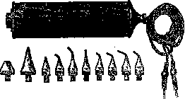
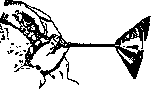
Figure 1. Hirschberg's hand-held electromagnet.
of the latter in 1879, a hand-held electromagnet weighing 250 g was first constructed from a soft iron core, about 10 cm long and 1-2 cm thick, with two curved tips and a winding of copper wire, through which an electric current was passed from a galvanic battery of several zinc-carbon cells (Fig. 1). Subsequently, this initial model underwent continuous improvements, primarily in the sense of increasing the power of the electromagnet by gradually increasing the weight of the iron core to 2.5 kg, i.e., to the limits allowing its manual use, as well as by increasing the number of turns of copper wire. Furthermore, the uninterrupted operation of the device was achieved by sequentially switching its power supply from a galvanic battery to an accumulator, and then to direct current obtained from the city network through transformers. Finally, instead of two poles in the form of permanent tips constituting one whole with the iron core, all subsequent models of both Hirschberg himself and other authors began to be supplied with a whole assortment of tips of various shapes and sizes, screwing onto one end. But hand-held magnets (Fig. 2), even of the improved type, possess a weak attractive force, acting at a distance of a maximum of 2-3 mm, and even then only on the condition that the fragment is in a free state. To extract intraocular foreign bodies with the help of a hand-held electromagnet, the tip of the device must be inserted into the eye cavity until it comes into direct contact with the metal fragment (intraocular method of foreign body extraction according to Hirschberg).

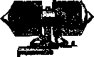
Figure 2. Hirschberg's hand-held electromagnet.
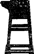
Being a great achievement in the field of eye surgery and yielding about 70% successful results, the electromagnet is at the same time not devoid of significant drawbacks. The introduction of the tip into the eye until it touches the foreign body is possible only under the control of a mirror and in the presence of complete transparency of the refractive media. In addition, the introduction of the tip into the eye is inevitably accompanied by the infliction of a new injury in the form of the expansion of the existing wound or a new incision of the sclera for the introduction of the tip, which often entails hemorrhage into the eye cavity, loss of the vitreous body, and the introduction of infection into the eye. In order to eliminate the indicated drawbacks, Haab proposed using more massive, or "giant," electromagnets, possessing greater power and greater attractive force, which makes the introduction of the magnet tip into the eye unnecessary, and the latter is only brought close to its pole. This method of extracting foreign bodies is called the "extraocular" method, or the Haab method. The basic requirements that giant electromagnets adapted for eye operations must satisfy are reduced to the following: maximum magnetization of the iron core by electric current, instantaneous activation of the magnet and cessation of such by rapid closing and opening of the current, the shape of the magnet itself and its poles, allowing...
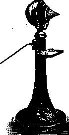
Figure 3. First model of Haab's giant electromagnet.
the greatest concentration of force lines for a distance of up to 25 mm from the pole to the eye, and at the same time high magnetic saturation of the metal fragments located in the eye. In 1894, with the assistance of Professor of Physics Kleiner, Haab built his first model of a giant electromagnet adapted for eye operations and which received wide practical application. This model consists of a shaft-like core of soft iron, with ends cut in the form of blunt cones, weighing 30 kg, 60 cm long and 10 cm thick; at the ends of the core are mounted two coils wound with copper wire 2 mm thick. Closer to the poles of the magnet, the coils are also obliquely cut
and the winding is reduced
-1 so as not to interfere with the free view of the operating field. The magnet is mounted on a wooden stand and can rotate around a vertical axis. A direct current with a strength of 6-8 amperes and a voltage of 50-60 volts is passed through the winding, which is switched on and off with the help of a pedal device by the operator's foot, so that both his hands remain free (Fig. 3). The second model of Haab's electromagnet differs from the first by a significant shortening of the core and the presence of one pole, whereas the opposite end of the magnet is enclosed in a hemispherical shell, which to a significant degree contributes to the best concentration of force lines in one direction and preserves the energy of the device (Fig. 4). This same Haab model, reinforced with the help of a fork rotating around its axis on a metal rod with a counterweight and installed on a vertical stand, possesses mobility in all directions and is adapted for operations on a recumbent patient, although Haab himself considers such an adaptation even unnecessary. Subsequently, he added to his model another small device in the form of a small steel rod with a pointed end, which, being introduced into the magnetic field of the large magnet, acquires the properties of a strong hand-held magnet; the rod is held in the operator's hands, which makes it possible to freely manipulate it in all directions, as well as to operate on patients in a recumbent position; in order to avoid its attraction to the pole
Figure 5. Additional rod for Haab's giant electromagnet.
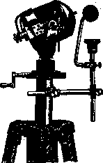
of the magnet, an intermediate steel rod is included between the latter and it, which also possesses sufficient mobility (Fig. 5). Haab's idea soon received wide recognition, as a result of which a whole series of new more or less improved models of giant electromagnets appeared, among which the following deserve the greatest attention: 1. Schlosser's model, improved by Edelmann (1903), represents, like all subsequent models, a single-pole magnet with an iron core of conical shape, 13 cm long and 5 cm thick, wound with approximately 500 turns of copper wire, with the front surface of the magnet covered by a convex iron plate 4 cm thick and 11 cm in diameter. The maximum current strength that the device can withstand for a short time equals 12 amperes. With the help of a metal fork, the device is mounted on a wooden stand and possesses full mobility in all directions (Fig. 6). 2. Schumann's model, similar to the previous one,
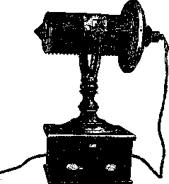
Figure 6. Schlosser's electromagnet. Figure 7. Schumann's electromagnet.
differs in principle only in that the inactive pole is covered with an iron plate for better concentration of the lines of force (Fig. 7). 3. The Volkmann model, or so-called hanging magnet, in its latest modification has an iron core 55 cm long and 7.5 cm thick, with reinforced winding on the working pole, so that the total diameter of the magnet, equal to 10 cm, reaches 15 cm at this end, and its total weight is 28 kg. The device requires a current of 6 amperes for full excitation, and can withstand double the load for a short time. The magnet has 3 screw-on tips of different shapes, namely: flat, hemispherical, and pointed. The entire device is suspended from a metal bracket fixed to the wall and is equipped in such a way that, while maintaining maximum mobility in all directions, it can assume both a vertical position, for surgery on a recumbent patient, and a horizontal one, for surgery in a sitting position (Figs. 8 and 9). 4. The Wagenmann model, of a rounded, approximately ellipsoidal shape, with a cutout on one side, 26.5 cm long. The iron core of the magnet with a diameter of 8 cm has a winding of copper wire 3 cm thick, which increases to 5 cm in thickness towards one pole with a cone-shaped unscrewable tip. On the opposite end of the cutout, an iron plate 1 cm thick and 22 cm in diameter is attached. The device
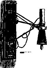
Fig. 8. Hanging electromagnet by Volkmann in the vertical position.
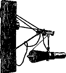
Fig. 9. Hanging electromagnet by Volkmann in the horizontal position.
withstands a current of 20 amperes and rests on a wooden stand with three legs. The patient is seated in such a way that his head is placed in the cutout of the magnet, between the two poles, with the injured eye brought close to the point of the tip (Fig. 10). 5. The intra-polar magnet of Mellinger-Klingelfuss, representing a closed solenoid of oval shape made of a very large number of turns of copper wire, 1 mm thick, without an iron core, with an aperture in which a person's head can be freely placed. To enhance magnetic induction, the coil is covered on the outside with an iron rim. The solenoid is mounted on a heavy iron stand and can rotate around a vertical axis. For the removal
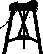
Fig. 10. Giant electromagnet by Wagenmann. of a foreign body, the patient's head is placed in the aperture of the solenoid, where, when an electric current is passed, a homogeneous magnetic field is formed, reaching its greatest density approximately in the center of its aperture, as a result of which the foreign body in the patient's eye is subjected to maximum magnetization. As an anchor for extraction, rods of soft iron of various thicknesses are used, which, being introduced into the magnetic field, are also subjected to magnetization, and their attractive force increases with an increase in their thickness. To achieve the greatest effect, an anchor bent in the shape of a horn is used, one end of which is fixed immovably on the outside, and the other is introduced into the center of the solenoid aperture until it touches the eye. The intensity of the device's action is regulated by the strength of the current passed, the thickness of the iron rods used as an anchor, and their distance from the injured eye. The advantages of the intra-polar magnet consist in the greatest concentration of lines of force, maximum magnetic saturation of the fragment inside the eye, and free visibility of the surgical field (Fig. 11). The main difference of the method of
Fig. 11. Intra-polar electromagnet by Mellinger-Klingelfuss.
extraction of foreign bodies from the eye with the help of giant electromagnets consists in the fact that the latter, possessing a powerful attractive force, act at a distance and make it unnecessary to introduce the magnet tip into the cavity of the eye. A. Strukov.
ELECTROMEDICAL DEVICES for therapeutic purposes, apparatuses in which electromagnetic energy is used in its most diverse manifestations. These include apparatuses for treatment with heat, light, electricity, X-rays, etc. For heat treatment, the following are used: a hair dryer, a thermophore (electric heating pad), a dry-air bath (see Heat treatment), etc. In light therapy practice, the following have become widely used: the Minin reflector, local light baths, general light baths, the Sollux lamp, the Elektro-sol lamp, a spotlight, mercury-quartz lamps by Bach, Jesionek, and Kromayer, and others (see Mercury-quartz lamp). In electrotherapy (see), galvanic elements, accumulators, direct current dynamos, as well as devices with current rectifiers (kenotrons) are used to obtain galvanic current. Apparatuses with batteries of galvanic elements are stationary (40-50 Leclanché elements) and portable (30-40 Grenet elements). In physiotherapy institutions, converters are used if the central station (city) provides alternating current, or current directly from the central station if the latter provides direct current. It is best to use accumulators. Distribution boards are used to conduct current to the patient. The voltage of the galvanic current should be in the range of 70-90 V (see Galvanization). Instead of universal apparatuses of the multostat or pantostat type (see), universal apparatuses are manufactured here in the form of boxes or boards providing galvanic, faradic, and sinusoidal currents. They are usually powered by alternating current from the electrical network. Galvanic current is obtained from them by rectifying the alternating current through kenotrons, sinusoidal current through a step-down transformer, and faradic current through an induction coil. These same apparatuses also have current for so-called cautery and endoscopy. With the help of small electric motors operating on alternating or direct current, vibration massage can be obtained (see Massage). Such small motors are also present in the converters on pantostats. A long flexible shaft is attached to the motor axis, at the end of which there is an eccentric or a crankshaft. Special tips, hard or soft (rubber), of various shapes for different parts of the body are put onto the latter. By the movement of the motor, these tips are brought through the flexible shaft into rapid oscillation, which is transmitted to the skin and tissues of the patient. For electro- and light therapy at home, portable equipment has currently been designed. For treatment with high-frequency currents, diathermy apparatuses, d'Arsonval apparatuses (see d'Arsonvalization), and in recent years short- and ultra-short-wave diathermy (see Ultra-short waves) are successfully used. Static machines (see Electrotherapy) have become widely used for treatment with static electricity (franklinization). For X-ray apparatuses, see X-ray technology.
Related articles
Mentioned in
Cite this page
“Electromagnet.” Soviet Medical Encyclopedia. English translation of Bolshaya Meditsinskaya Entsiklopediya, 1st ed. (Moscow, 1928–1936), ed. N. A. Semashko. https://sovietmedicalencyclopedia.pages.dev/article/electromagnet/