Basins
Historical document, translated for reference. It reflects medical knowledge of the 1920s–30s and is not medical advice.
Summary
This 1930s Soviet encyclopedia article examines basins from hydrological and sanitary engineering perspectives, detailing river catchment areas, water supply sedimentation basins, and wastewater settling tanks.
Encyclopedia article (1928–1936)
BASINS. Usually, basins are distinguished with regard to 1) hydrology and 2) sanitary engineering. In hydrology, river catchment basins are distinguished, and in sanitary engineering (in water supply and sewerage)—settling basins. I. A river catchment basin is the entire territory (area of the earth's surface) from which atmospheric precipitation naturally flows into a river along the valley slopes of the river itself and all its tributaries. Water flowing at any specific location (cross-section) of a river along its course is gathered only from a certain part of the entire river basin (from which atmospheric precipitation flows into the river in the entire upstream section of the river). This part of the river basin is the catchment basin of the river for its given location (section). In the case of an artificial reservoir formed, for example, by a dam, its basin (catchment basin) is the entire surface area from which atmospheric precipitation flows into the reservoir. In the sanitary respect, the establishment of the boundaries of a basin is very important because, strictly speaking, throughout the entire basin of that part of the river which lies upstream of the water intake of the water supply system, and throughout the entire basin of the reservoir (or, at least, in the part closest to the intake, determined by preliminary sanitary and technical surveys), it is necessary to establish sanitary and technical supervision. In addition, a certain technical preparation of the reservoir basin (during the construction of the latter) may be of importance for the physico-chemical qualities of the water collected in the reservoir. In the flow of groundwater for any cross-section, the catchment basin will be the entire region that serves to feed the flow above this cross-section (see Artesian waters). II. Settling basins in water supply represent reservoirs for periodic or continuous settling. Periodic settling is called that when the basins are filled and, after the water has settled, are emptied. Continuous settling occurs with a constant slow flow. In periodic settling, the settling basin represents an open reservoir dug in the ground with a bottom and walls covered with stone, clay, concrete, and other waterproof materials. In continuous settling, the settling basin is an underground reservoir constructed of stone, usually of reinforced concrete, open or closed, with a length of approximately 50-100 m, a width of about 25-50 m, divided by thin circulation partitions into individual longitudinal corridors about 5 m wide each, for better direction of the water and its sufficiently uniform distribution among the individual corridors. Therefore, the water entering the settling basin is directed first through the receiving chamber into the transverse corridor, through the openings (weirs) of the latter it diverges into individual longitudinal corridors, at the end of the settling basin it overflows again through the openings into another transverse corridor and from it is already discharged to the filters. The length of the settling basin L is determined by the time t and the settling velocity v. If v is cm/sec, t is hours, L is meters, then L = (t · v · 60 · 60) : 1000 = 3.6 t · v. The cross-section of the basin f in m2 is determined by the velocity v and the amount of water S settling per day (cubic cm): f = S : (24 · a · 60). In turn, a = B · h, where B is the width of the settling basin, and h is the useful depth of the water. They take h within 2.5–4.5 m, with the lower limit referring to closed settling basins and the higher to open ones. The total depth of the settling basin is greater than h by the thickness of the sediment layer h1. Knowing from analyses the amount of suspended impurities in the settling water and taking into account the time interval between two successive cleanings of the settling basin, h1 can be found. Cleaning of the settling basin is usually rare (2–3 times a year). The amount of sediment precipitating from the water decreases as it moves through the settling basin, by virtue of which the bottom of the latter (in order to maintain a constant water velocity) is given a uniform rise i = 0.005–0.02 m towards the direction of movement. This is very important from a sanitary-technical point of view, since it prevents the washing out of already settled sediment from the settling basin, which could take place with an increase in velocity in any cross-section narrowed by sediment. In addition, at the end of the settling basin, lighter impurities that drop very slowly precipitate from the water; for them, it is useful to have a smaller depth of the settling basin. Sediments are removed from the settling basin usually manually and discharged through mud channels directly into the river (below the water intake) or onto special sludge beds for drying. The cost of closed settling basins is approximately 40–80 kopecks per 1 cubic meter of their capacity. Open settling basins are cheaper, but from a sanitary point of view, they are significantly worse than closed ones. (Vertical settling basins for settling during coagulation—see Coagulation.)
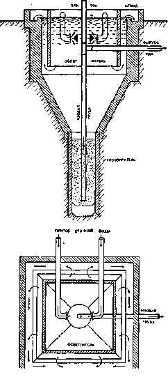
Figure 2. Imhoff-type clarifier (with vertical water movement). The working effect is the same as that of clarifiers with horizontal water movement. Depending on some design details, systems differ—Dortmund systems, Neustadt wells, Kremers wells, etc. Sludge from clarifiers and settling wells is discharged for drying onto sludge beds or sent preliminarily to sludge digesters.
P. Belov. Settling basins in sewerage; characteristics from a biochemical point of view. Clarifiers, as structures for preliminary wastewater treatment, have a great influence on subsequent biological treatment, since processes of biochemical decomposition of the liquid waste and the sediment separated from it begin already in the clarifiers. Clarifiers, the design and forms of which are very diverse, are basins calculated to reduce the velocity of the liquid flowing through them to such an extent as to cause suspended substances (sediment) to precipitate to the bottom of the clarifier. With a horizontal direction, the flow velocity usually ranges between 1 and 10 mm per second; the "exchange period" (the time of passage of the liquid through the clarifier) is from 2 to 6 hours. Under these conditions, it is possible to retain 60 to 75% of suspended substances, depending on the concentration of the liquid. The clarifier must be provided with a certain reserve volume for the precipitating sediment and adapted for convenient periodic (every 5–15 days) removal of the sediment (see Figure 3). But the role of the clarifier is not limited to the retention of suspended substances; with its significant volume, the clarifier equalizes the composition (smooths out fluctuations) of the liquid flowing through it, which is of very great importance for the smooth operation of oxidizers receiving the liquid clarified in the clarifier. The smaller the water inflow to the biological station and the greater the fluctuations in its composition, the more useful it is to increase the water exchange period in the clarifier. One should not forget that primary biochemical and physicochemical changes in wastewater begin even in the supplying channels and pipes and that these changes continue in the clarifiers. These include hydrolytic processes (e.g., urea hydrolysis), exchange decomposition reactions (from the admixture of industrial or
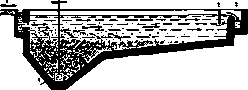
Figure 3. Scheme of a clarifier with horizontal
flow: 1—liquid inlet; 2—semi-submerged partition; 3—clarified water outlet; 4—sediment outlet. soapy waters), changes in the degree of dispersion of colloids, their adsorption, changes in the active reaction (see). All these phenomena, especially in the case of a short pipeline to the station, also proceed in the clarifier. Therefore, it is clear what importance an increase in the exchange period acquires in this case, while the situation in the clarifier is complicated by the biochemical processes of sediment decomposition, the liquid and gaseous products of which enter the wastewater flowing through the clarifier. This latter circumstance is considered for the most part unfavorable for the subsequent treatment of the liquid, and therefore requires the removal of the sediment as frequently as possible in a "fresh" (undigested) form. Such "fresh" sediment has a disgusting odor, a slimy consistency that makes drying difficult, and is an attraction for flies. This makes the treatment of "fresh" sediment the weakest and most troublesome spot in both sanitary and technical respects. Only economy in the dimensions of the clarifiers forces one to put up with it (see Wastewaters). In this regard, the so-called septic tank, septic, or putrid basin, or
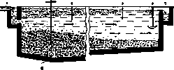
Figure 4. Scheme of a septic tank: 1—liquid inlet; 2—semi-submerged partitions; 3—clarified water outlet; 4—sediment outlet. On the surface—floating crust, on the bottom—rotting sediment.
simply a "septic tank," the task of which consists, along with the separation of sediment (function of a settling basin), in its biochemical destruction. This is achieved through anaerobic microbial processes and leads (under favorable conditions) to the fact that part of the organic matter (suspended and colloidal) is fermented with the release of soluble and gaseous products, and the volume of the sediment decreases; it loses the mucous consistency inherent in fresh sediment and gives up water more easily. As for the stench, the septic tank is characterized by the smell of H2S, which is released from both the septic tank and the sediment. But since sediment is discharged from the septic tank only 1-2 times a year, the inconvenience in this regard is significantly less than in the case of "fresh" sediment. The septic tank is calculated for a period of liquid exchange of no less than 12 hours, and for the most part 24 hours, with a correspondingly low flow velocity (see Figure 4). The volume of the septic tank must be calculated for the storage of the separated sediment between two cleanings (mostly 2 times a year), i.e., approximately for a 6-month amount of sediment, which is retained in the septic tank somewhat more strongly than in a conventional settling tank, and which in its main mass is distributed along the bottom of the septic tank (but partly floats up, sometimes forming a very thick crust). This makes it necessary to give septic tanks sufficient depth (over 2 m). Under these conditions, an anaerobic environment is created throughout the entire thickness of the water and sediment, with the exception of only the very surface layer of water (and crust). The septic tank is most characterized by hydrolytic and reduction processes, which strongly alter the nature of the "sediment." Proteins are peptonized, converted into amino compounds and ammonium salts. Fats are saponified. In general, the process proceeds towards the destruction of some part of the organic matter molecule down to CO2 with the release of reduced products in the form of sulfur compounds, ammonium salts, salts of fatty acids, and complex carbonaceous "humic" substances. CH4 (methane), H2, CO2, and H2S are released as gases from the septic tank. Reduction processes capture oxygen compounds of nitrogen (nitrates), S (sulfates), and Fe. In particular, Fe is bound in the sediment by H2S in the form of iron sulfide, which colors the sediment black. The liquid flowing out of the septic tank may be transparent and colorless, but, being saturated with H2S, it opalesces and very often, carrying along particles of black sludge (thus disrupting the settling process), is colored dark. In this case, it is easy to obtain a liquid from the septic tank with a larger amount of suspended solids and with a greater oxygen demand than "raw" wastewater, and therefore difficulties may arise with its subsequent purification. The decomposition of sediment in a properly functioning septic tank undoubtedly reduces its volume, but hardly by more than 30%. At a sufficient distance from dwellings, the septic tank does not require a cover, which is often created by the formation of a crust. A cover is necessary if the septic tank is located close to residential buildings; then the stinking and flammable gases released from the septic tank, which easily form an explosive mixture with air, require good ventilation under the septic tank cover. Exhaust pipes must not be connected to chimneys. When cleaning the septic tank, special attention should be paid to the possibility of H2S poisoning of workers who come into contact with the sediment and are inside the septic tank. This circumstance should generally be kept in mind during any work in sewer structures where sediment deposits are present. Well-rotted sediment removed from the septic tank gives up water (dries) quite quickly, but it is produced immediately in a large mass, requires a correspondingly large area for drying, emits a pungent H2S odor in the first days, and attracts flies. Recently, for the preliminary treatment of fecal and domestic waters, the septic tank has been giving way to more advanced devices, but it has by no means lost its significance in the case of treating certain "industrial" waters and finds application even for fecal and domestic waters when "smoothing out" of the flow rate is required, when there are no chances for the skilled operation of newer devices, and when the issue of odor is not very acute. A combination of a simple settling basin with a septic tank (or rather, an improvement of the septic tank) is represented by the designs of two-story settling tanks proposed in Germany by Imhoff (1907) and in England by Travis (1906). The Travis hydrolytic basin (Travis tank) in its original design (Norwich) consists of a rectangular reservoir, on the sides of which are settling compartments communicating through openings with a rotting chamber located beneath it, where the sediment separated in the settling compartments falls through the indicated openings. In this way, the clarified liquid is preserved in a "fresh" state. Through the settling tank, 4/5 of the entire liquid is passed (exchange period about 3 hours). In addition, so-called colloidors—wooden plates creating a large surface for the adsorption of colloidal impurities from the flowing liquid, which slide in the form of clots from the collidor plates into the rotting chamber—are suspended in the settling compartments. A flow of wastewater in the amount of 1/5 of the total mass is constantly maintained through the rotting chamber (exchange period about 12 hours). This is a characteristic feature of the Travis tank. Finally, 4/5 of the clarified liquid and 1/5 from the rotting chamber are mixed and jointly pass through a third compartment—the hydrolytic chamber (also with a collidor), in which the process ends. The Travis tank gives a good clarification effect, but, probably due to the complexity of the design, it has not become widespread. Information regarding the quantity and quality of the resulting sediment is very contradictory. In Luton (England), the basin compartments are arranged concentrically around a central well serving for sludge discharge. (Travis tanks of this shape have been installed in Kharkov and Simferopol.) The design developed by Imhoff for the treatment plants in the Emscher River region (Ruhr area) has become known in our country as the Emscher basin (Emscher Brunnen) or Emscher well (see Figure 5). The Emscher basin in its typical form represents a deep reservoir (up to 8-10 m) consisting of two cylindrical basins with a conical bottom. In their upper part, there is a sediment compartment in the form of 1-2 troughs communicating by a long slot with the underlying rotting compartment. The exchange time in the troughs usually ranges from 1 to 3 hours (speed as in a settling tank). The sludge (rotting) compartment is designed for a long stay of sludge (from 2 to 6 months). In the Emscher basin, there is no constant flow of wastewater through the sludge compartment; wastewater enters there only periodically in connection with the discharge of part of the rotted sludge. The anaerobic decomposition of sediment in the sludge compartment of the Emscher basin under normal conditions proceeds in an alkaline environment and is characterized by the absence of H2S in the released gases, which consist mainly of methane (up to 80%) and CO2 (15%). The sediment decomposition process is a combined fermentation, the first phase of which is the formation of fatty acids from proteins, carbohydrates, and fats, and the second phase is their fermentation to methane. The process proceeds correctly only if the physicochemical environment is favorable for both groups of microbes participating in it. Otherwise, if the participation of the second group is weak, the decomposition process proceeds abnormally: acidic fermentation occurs with the release of H2S, expressed by the floating of the sediment and its swelling to such an extent that it enters the troughs and completely disrupts the operation of the Emscher basin. One of the conditions for the proper operation of the Emscher basin is good mixing of newly incoming sediment with old, well-fermented sediment. The rate of sediment decomposition strongly depends on the temperature of the air and wastewater, which is therefore of great importance in the calculation of the sludge compartment (it determines the time the sediment stays in it). Sediment from the Emscher basin under proper fermentation is removed periodically, in small portions, every 7-10 days. Usually, for this purpose, the hydraulic head is used by arranging the external opening of the sludge pipe, which sucks the sediment from the very bottom, 1.5-2 m below the water level in the Emscher basin. Due to the great depth, the mature sediment contains a small amount of water—the volume of the mature sediment is about 10 times less than in the fresh state. The odor of mature sediment resembles the smell of asphalt, burnt rubber, sealing wax; this odor does not act as an attractant for flies. The sediment loses
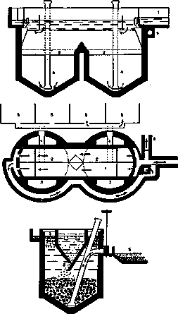
Figure 5. Schematic plan of the Emscher basin: 1—liquid inlet into the settling flow; 2—longitudinal slot at the bottom of the trough; 3—"gas vents" (where the "crust" collects); 4—sludge pipes; 5—drying beds; 6—clarified water outlet. The arrangement of the supply and discharge channels allows the liquid to be run in the reverse direction.
its ... sediment from the Emscher basin during proper fermentation is removed periodically, in small portions, every 7–10 days. Usually, this is done using hydraulic head by placing the outer opening of the sludge pipe, which draws sediment from the very bottom, 1.5–2 m below the water level in the Emscher basin. Due to its great depth, mature sludge contains a small amount of water—the volume of mature sludge is about 10 times smaller than in its fresh state. The odor of mature sludge resembles the smell of asphalt, burnt rubber, or sealing wax; this odor is not attractive to flies. The sludge loses

Figure 6. Emscher basin with a device for capturing illuminating gas from "gas vents".
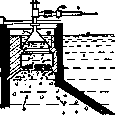
also maintains its mucous consistency. As a result, the sediment from the Emscher basin dries quickly, does not spread stench, and requires less area for drying. Recent improvements to the Emscher basin are aimed at utilizing illuminating gas (see figures 6 and 7). Under favorable temperature conditions, 8 liters of gas per inhabitant per day are obtained, possessing a high calorific value (up to 7,000–8,000 thermal units). In many German cities, the sale of gas partially offsets the costs of the treatment plant. The Emscher basin is one of the most advanced devices for the preliminary treatment of wastewater, but it requires very careful maintenance, like any device based on the use of biochemical processes. Recently abroad, a sludge digestion chamber separated from the settling tank (separate sludge digestion) is increasingly used, the task of which is only the digestion of sludge. The biochemical process characteristic of this device—methane fermentation—makes it possible to call the structure itself a methane tank (see figure 8). For Figure 7. Detail of the device for gas capture: 1—settling trough; 2—wooden grate; 3—iron cone; 4—gas pipe.
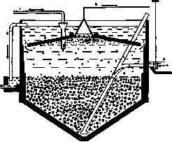
Figure 8. Reservoir for separate sludge digestion ("methane tank"): 1—inlet of "fresh" sludge; 2—reinforced concrete ceiling with an opening covered by a wooden grate; 3—sludge pipe for rotted sludge; 4—drying bed; 5—gas pipeline from the dome; 6—drain pipe for excess liquid; 7—openings for the exit of excess liquid.
To reduce the volume of the structure, such chambers are built with artificial heating, for which the illuminating gas leaving the methane tank is used. (Literature is cited in the article Biological method of wastewater treatment.)
Related articles
Mentioned in
- American Filters
- Artesian Waters
- Automobile Exhaust
- Barbus Fluvialis
- Biological Method of Sewage Treatment
- Bithynia
- Bitter-Salt Lakes
- Boxes (Hospital)
- Brine
- CAPTAGE
- Convection
- Decerebration (DECEREBRATION)
- Electrotherapy
- English Filters
- Extinction
- Gas Production
- Irrigation Fields
- LIMANS
- Mountain-Sanitary Protection
- Mud Treatment Areas
Cite this page
“Basins.” Soviet Medical Encyclopedia. English translation of Bolshaya Meditsinskaya Entsiklopediya, 1st ed. (Moscow, 1928–1936), ed. N. A. Semashko. https://sovietmedicalencyclopedia.pages.dev/article/basins/